

Precisa de conectores à prova d'água?Solicite um orçamento →
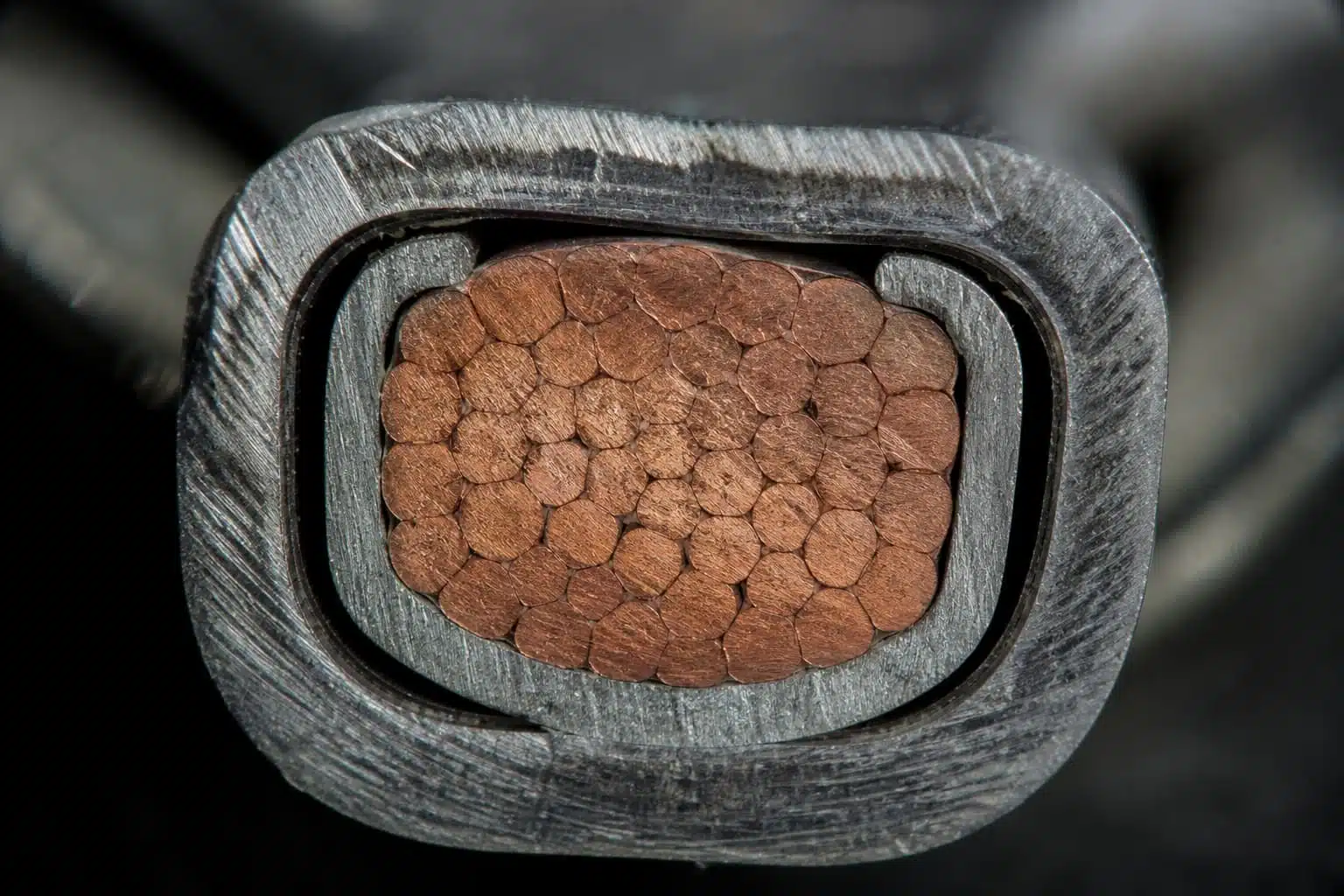
Crimp vs. solder solar connectors is the most common termination question, and there’s no blanket answer: follow the terminal’s qualified termination method. For connector terminals designed for crimping, a qualified crimp with the terminal, cable, and crimp tool specified by the manufacturer is normally the preferred joint. The crimp is part of a certified system: IEC 62852 and UL 6703 qualify the contact, conductor, and tooling together, and a controlled crimp forms a gas-tight metal-to-metal connection that survives thermal cycling. Do not add solder unless the connector manufacturer explicitly permits it, because solder wicking and stiffness can shift stress into the cable and make process control harder. For solder-designed terminals, follow the manufacturer’s instructions instead.
The answer depends on how the terminal was designed, not on personal preference. A crimp-designed terminal has a barrel shaped for compression, a plating chosen for cold-weld contact, and a qualification record that lists the exact cable and tool combinations. A solder-designed terminal, such as a solder-cup or ring terminal, has geometry and plating chosen for wetted joints. Each method is certified for the terminal it was designed with; mixing them usually lands outside the certificate.
For solar connectors, the practical rule is simple: check the datasheet or assembly instruction before you choose. If the manufacturer lists crimping with a specified tool, crimp. If soldering is listed or explicitly permitted, solder per the instruction. If the datasheet is silent, treat crimping as the default, because virtually all MC4-compatible and PV4-style solar connector contacts are crimp terminals.
The stakes are higher in PV than in low-voltage indoor work. A string runs at up to 1500 V DC, is energized whenever light hits the modules, and sits outdoors for twenty years of thermal cycling and vibration. PV cable termination is the joint where current transfers from the conductor to the terminal, and it is the same joint the certificate covers when it was made with the specified process.
Key Takeaway: A crimp creates a gas-tight “cold weld” connection, sealing out oxygen to prevent corrosion and long-term electrical resistance build-up.
A crimp works by compressing the terminal barrel around the conductor until the strands deform and metal touches metal at many points. The result is a gas-tight connection: the interface is sealed against oxygen, so corrosion cannot creep in and raise resistance over time. This is the cold weld that gives crimping its name.
The electrical part and the mechanical part are the same joint. Current transfers across the compressed interface, and its quality shows up as contact resistance; the mechanical part holds the conductor against vibration and pull. A connector maker rates the whole system, housing included: the PV4 series is rated up to 65 A with 10 mm² cable under TÜV test conditions, and the connector carries current only as well as the cable crimped into it.
Standards treat the crimp as a system. IEC 62852:2014+AMD1:2020 CSV, the standard for connectors in DC circuits of PV systems (such as standard MC4 connector designs), and UL 6703 in North America qualify the contact, the cable size, and the crimp tool together. Change any element and the certificate no longer covers the combination, which is why the approved tool and die matter: they are part of the tested system. Wikipedia’s description of crimping covers the general mechanics; the PV version adds certification and environmental requirements.
Exploring the subtle risks, mechanical changes, and field compliance issues behind soldering vs. crimping.
Soldering looks attractive for the same reason it is risky: it fills gaps. Molten solder flows around the strands, and a freshly soldered joint often measures lower resistance than a crimp. That initial reading hides four problems.
Solder wicks by capillary action up between the strands of a stranded conductor. The wetted section becomes stiff, so bending and vibration concentrate strain at the hard-soft transition just outside the barrel, which is exactly where field failures show up as broken strands.
Bending & vibration strain concentrates at the hard-soft transition outside the barrel.
High soldering heat can damage insulation at cable entry points and anneal copper.
Flux residue absorbs moisture over time, slowly corroding the internal joint.
Joint deformation under thermal cycling can create voids and increase resistance.
The heat of soldering can also damage insulation at the cable entry and anneal the copper. Flux residue absorbs moisture and can corrode the joint over years. Solder also creeps under thermal cycling: the joint slowly deforms, voids form, and resistance climbs. None of these problems show in a quick resistance check, and all are hard to control on a rooftop.
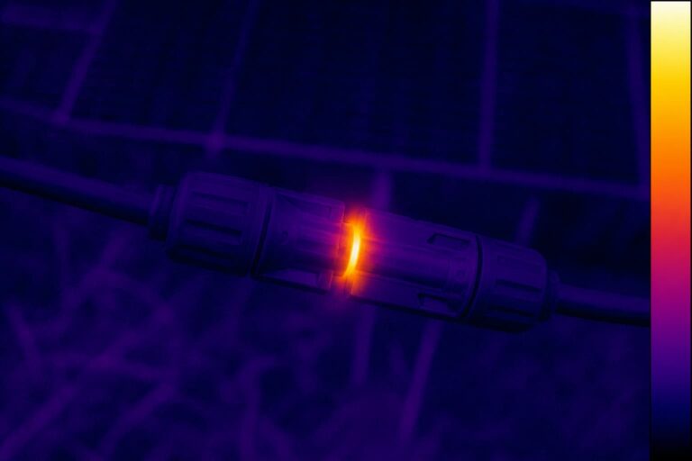
There is a certification dimension as well. A hand-soldered joint on a crimp-designed PV connector has no certificate coverage under IEC 62852 ou UL 6703, because the qualification was done for the crimp system. It may work for a season, then turn into a hot spot under thermal cycling.

None of this means soldering is always wrong. Some terminals are designed for soldering, and some manufacturers explicitly permit soldering for their contacts. The distinction is the datasheet, not the tool on the bench. If the terminal drawing lists soldering as an approved termination, follow the manufacturer’s soldering instructions: temperature, flux, dwell time, and cleaning. Factory-controlled soldering with defined parameters is different from a hand-soldered field joint, because the process is reproducible and inspected.
The mistake to avoid is adding solder to a crimp-designed terminal “for extra security.” The extra material does not reinforce the joint. It changes the joint the terminal was designed for, removes certificate coverage, and creates the wicking and strain problems above. If a crimp tool is not available, stop and get the tool before you assemble.
The crimp vs solder solar connectors question comes down to seven factors.
Decision matrix: qualified crimp vs soldered joint
| Factor | Qualified crimp Recommended | Soldered joint |
|---|---|---|
| Certificate coverage | Contact, cable, and tool certified together under IEC 62852 / UL 6703 | No certificate coverage for hand-soldered PV connectors |
| Mechanical strength | Gas-tight cold weld; proven under thermal cycling and vibration | Solder creeps under thermal cycling; voids form over time |
| Strain distribution | Barrel holds the strands uniformly | Solder wicking stiffens the conductor; strain concentrates at the transition |
| Repeatability | Tool + die + full stroke gives the same result every time | Depends on operator skill, temperature, flux, and timing |
| Inspeção | Crimp height, pull test, cross-section, resistance | Visual only in the field |
| Best use | Crimp-designed PV terminals (MC4-compatible, PV4 series) | Terminals the manufacturer specifies for soldering; controlled factory processes |
| Field conditions | Ratchet tool with matched die | Not a certified substitute in outdoor DC circuits |
For field work, the tooling question is simple: use the manufacturer’s approved ratchet crimper with the die matched to the exact cable size, and complete the full stroke. The ratchet prevents the tool from opening until the stroke is complete, which guarantees consistent force from crimp to crimp; if it opens early, the crimp is incomplete by definition. Generic pliers-style crimpers have no locator and no stroke guarantee, so the contact can sit off-center, and the barrel can deform unevenly.
Production lines add controls that field work cannot: hydraulic heads for large conductors, crimp-height monitoring, first-article inspection, and traceability from contact lot to tool to operator. Our controle de qualidade page shows the checks we run on production lines; the same discipline is what makes factory-crimped cable assemblies a lower-risk choice for large projects.
For installers, the tool is part of the certificate. A tool that “fits MC4” is not the same as a tool approved for your contact family. When you buy connectors, ask for the recommended crimp-tool specification at the same time; we include it with the datasheet.
A good crimp is verifiable, and verification is where crimping beats soldering in practice.
Crimp height is the dimension across the compressed barrel after crimping. The datasheet gives an acceptable window; below it the barrel is over-compressed and strands may be damaged, above it the joint is loose and resistance is high. A caliper check takes seconds.
Pull force is the mechanical proof. Pull the cable against the contact with the force the exact contact and cable datasheet specifies; the contact must not move. There is no universal number, so do not use one from memory.
Cross-sectioning is the laboratory check: cut the crimp, polish it, and inspect under magnification. It shows strand compression, voids, and whether the barrel bottomed out on the conductor. Contact-resistance measurement in milliohms confirms the electrical side. These are qualification and incoming-inspection tools, not site routines.
For a field-made crimp, the minimum is visual inspection plus pull test, logged with tool, die, and operator. The step-by-step crimping procedure and the common mistakes list are in our guide on how to crimp MC4 connectors ; the verification section there matches this one.


| Failure mode | Cause | Consequência | Correction |
|---|---|---|---|
| Solder wicking into the conductor | Soldering a crimp-designed terminal | Stiffened conductor, strand fatigue at the barrel edge | Use the qualified crimp; replace a soldered terminal |
| Solder creep and voids | Thermal cycling over time | Hot spot, rising resistance | Replace with a crimped joint |
| Over-crimp | Wrong die or excessive force | Cracked barrel, damaged strands | Match die to the datasheet; one full stroke only |
| Under-crimp | Wrong tool or partial stroke | Alta resistência, superaquecimento | Ratchet to full release; pull test every crimp |
| Flux residue left on the joint | Soldering without cleaning | Corrosion, moisture absorption | Follow the specified termination; do not solder unless permitted |
| Insulation damage at the cable entry | Heat during soldering | Reduced dielectric strength | Inspect and replace damaged cable |
Request the terminal, cable, and recommended crimp-tool specification together, so the termination method is decided on the datasheet rather than on the roof. Send your system voltage, cable size, connector type, and quantity, and we reply with a quote and a matching datasheet within one business day.
Request the Terminal & Crimp-Tool SpecificationRecursos relacionados

VAMOS CRIAR SUA SOLUÇÃO DE CONECTIVIDADE
Share your application, specifications, and estimated quantity. Our team will recommend a suitable connector solution and provide a quotation.
Baixo MOQ · OEM e ODM · Suporte na seleção de produtos · Resposta rápida à solicitação de cotação