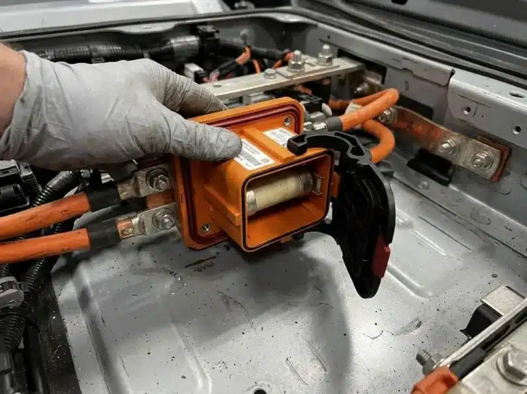


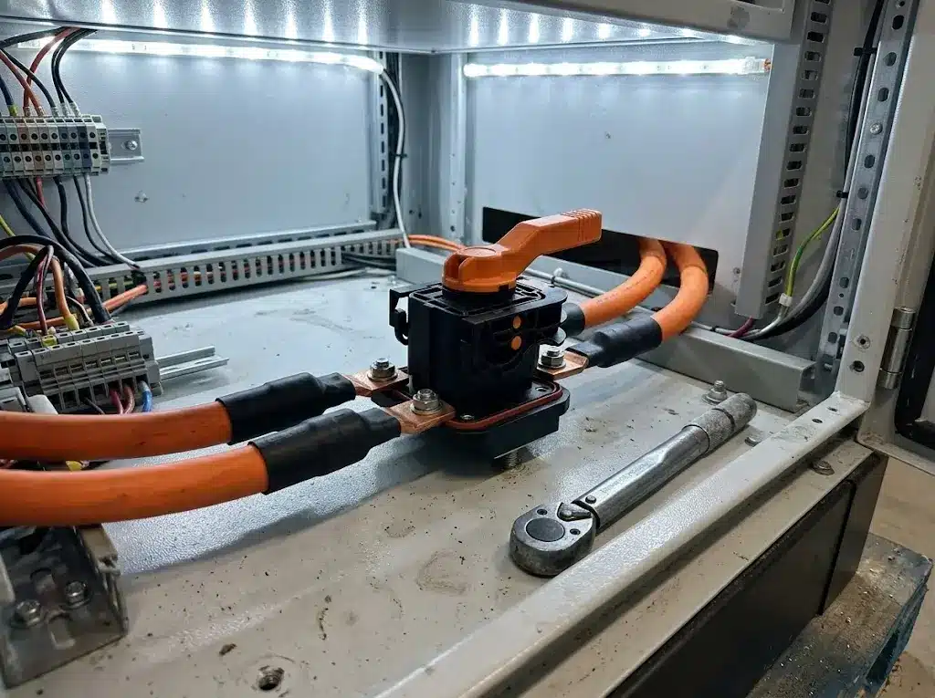
How to size a manual service disconnect is a four-step arithmetic problem, and every input comes from the pack rather than from the part. The first is the continuous current at the lowest working voltage. Then come the current still available at cabinet temperature, the highest voltage a charged string reaches, and a judgment on whether peaks are rare enough to ignore. On a 250 kW cabinet with a 400-cell LFP string the answer is 233 A. That leaves a 350 A frame about 36 percent of margin at 45°C.
An undersized isolator rarely fails on the day it is installed. The contacts run hot. The housing discolors over a season of cycling, and an inspection a year later finds a part that has been cooking at 20 K above its test condition. Four numbers, worked before a part number is chosen, prevent that. Manual service disconnect selection starts from the pack, and a product page checklist answers a different question.
| Input the calculation needs | Where the number comes from |
|---|---|
| Continuous power at the terminals | Converter nameplate, plus the auxiliary loads on the same bus |
| Lowest working voltage | Discharge cut-off of the string, multiplied by cell count |
| Highest working voltage | Charge cut-off of the string, multiplied by cell count |
| Ambiente del armario | Thermal test of the enclosure, not the room temperature |
| Sección transversal del cable | Lug drawing, and the range the device is rated with |
Working these steps out of order produces a part that looks adequate on paper and runs hot in service. Current decides which frame you are looking at. Voltage decides whether that frame is allowed at all, and temperature decides how much of the printed rating survives inside the cabinet.
Start on the battery side of the converter, because that is where the isolator sits. A 250 kW cabinet with a 97.5 percent efficient converter draws 256.4 kW from the pack at full output. Pumps, fans and the BMS add roughly 5 kW on top. Call it 261.4 kW passing through the disconnect.
Divide by the lowest working voltage rather than the nominal one. A 400-cell LFP string sits at 1,280 V nominal, but the converter keeps pulling full power at the discharge cut-off. Current climbs right before the BMS opens the main contactor. At 2.8 V per cell the floor is 1,120 V, so 261,400 W ÷ 1,120 V = 233 A.
Running the same load against nominal voltage gives 204 A. That 29 A gap is exactly the margin an undersized part consumes in its first hot season.
Battery energy does not enter this step at all. A 500 kWh pack at 1,280 V is a 391 Ah pack. Amp-hours say how long the current flows, not how much of it flows. Sizing from kWh divided by voltage is the most common arithmetic error here, and it always errs low.
Cable belongs in the same step, because the device rating was established with a conductor attached to it. Our product page pairs the 350 A frame with 95 to 150 mm² cable. Put a 50 mm² conductor on a 233 A load and the terminal heats even when the contacts are perfect. This is where how to size a manual service disconnect stops being about the device alone, and the eight-step guide for 1500 V BESS connectors covers the coupling if the cable is still open.
Three separate events push current above the steady figure. Treating them as one number drives engineers into a frame two sizes too large.
| Event | Typical size | Duración | What it actually loads |
|---|---|---|---|
| Converter overload | 110 to 150 percent of rating | 10 to 60 s | Terminal and contact interface |
| Pre-charge inrush | Several times rated current | Under 1 s, resistance limited | Lug and busbar, once per close |
| Load-following duty | Base to 140 percent, repeating | Hours, continuously | Everything, by RMS |
None of these reach the isolator while it is moving. NFPA 70 Article 706.15(E)(2) permits a bolted or plug-in disconnect that is not rated to break load. Our 350 A frame is an isolation device rather than a load-break switch: contacts separate only after the circuit is already dead. A peak heats the terminal and the contact interface. That belongs in the thermal check, not in a breaking-capacity check.
One 10 s event at 120 percent of a 250 kW rating reaches 279 A, inside a 350 A frame even after derating. Where peaks repeat within the hour, average them by the square root of the duty cycle instead of by time. A frequency-regulation profile of 250 kW for half the hour, 350 kW for 30 percent and 150 kW for 20 percent gives 251 A RMS. A straight time average would say 243 A, an 8 A gap that widens quickly on storage following a solar curve.
A pack built for repeated 150 percent events needs the peak treated as a second continuous rating. That is 348 A on this pack, which no longer fits a 350 A frame once the cabinet is warm.
Every printed rating has an ambient temperature attached to it, whether the datasheet states it or not. The current rating of an MSD comes from a temperature-rise test run at one room condition. Our own specification sheet for the 350 A frame lists the working range as -40 to 125°C, and that range is not a derating curve: it says where the part survives, not what it carries at 110°C.

Rather than a curve, we work to a planning figure of 0.46 percent of the rating per kelvin above 25°C. Twenty kelvins of extra cabinet heat costs about 9 percent of the rating, which is enough to move a marginal design down a size step. The specification sheet gives 350 A with no ambient reference and no curve, so this is the figure to carry until one arrives in writing.
| Ambient in the compartment | Usable from a 350 A frame | Against the 233 A load |
|---|---|---|
| 25°C | 350 A | 50 percent margin |
| 35°C | 333 A | 43 percent margin |
| 45°C | 317 A | 36 percent margin |
| 55°C | 300 A | 29 percent margin |
At 45°C the frame gives up 33 A and still covers the load, which is the kind of margin that survives a hot week in August. Ask for the reference temperature in writing, from us or anyone else, before the enclosure is frozen.
Heat leaves the contacts through the terminal, and the compartment decides how fast. A sealed steel compartment that reaches 45°C in August holds that temperature for hours. The temperature rise behavior of BESS connectors explains why cable size moves the same number in the other direction.
When the string’s charge cut-off climbs past the device rating, no current figure rescues the choice. A 1500V DC disconnect either covers the highest voltage the pack can produce, or the frame changes.
Take that highest figure from the charge cut-off, not from the nameplate. Four hundred LFP cells at 3.65 V per cell reach 1,460 V at the top of a charge cycle. A 1,500 V DC device therefore holds 40 V of headroom, or 2.7 percent. Forty volts is thin, and it is what a utility review asks for.
Change the string to 416 cells and the arithmetic breaks the device. 416 × 3.65 V = 1,518 V. That sits above the 1,500 V rating even though the pack’s nominal voltage looks comfortable. Series count, not the marketing voltage of the system, decides this check.
Three voltage figures appear on the specification sheet and they answer different questions. Mixing them is how a 6,000 V number ends up quoted as a working voltage.
| Number on the sheet | What it measures | What to check it against |
|---|---|---|
| 1.500 V CC | Highest continuous working voltage | 1,460 V charge cut-off |
| 6,000 V AC for one minute | Dielectric withstand of the insulation | Not a working voltage at all |
| >5,000 MΩ | Insulation resistance, quoted at normal temperature and humidity | Not a rating, a quality figure |
Segmentation under the 240 V DC rule is separate arithmetic, and it only applies when a pack has to be split for maintenance. It answers how many isolation points a string needs, while these four numbers answer what a single device must survive.
The four results line up on this cabinet: 233 A at the lowest working voltage, 279 A for a 10 s overload, 317 A available at 45°C, and 1,460 V against a 1,500 V rating. A 350 A frame covers the installation with 36 percent of current margin and 2.7 percent of voltage margin.

Specifying a second cabinet from the same part number runs into a ceiling. The same frame at 45°C carries 317 A, which on this pack equals 341 kW at the converter terminals. Push the same cabinet to 350 kW and the demand reaches 325 A, eight amps past what the frame can hold.
Inquiries usually run the other way: I already have this part, so how large a pack will it carry? Answering it is still how to size a manual service disconnect, with the same four inputs solved for power instead of for current. Hold the 1,120 V floor, efficiency and the auxiliary load constant, and vary the converter rating.
| Converter rating | Battery-side power | Current at 1,120 V | Verdict against 317 A |
|---|---|---|---|
| 150 kW | 158.8 kW | 142 A | Fits, large margin |
| 250 kW | 261.4 kW | 233 A | Fits, 36 percent margin |
| 300 kW | 312.7 kW | 279 A | Fits, 14 percent margin |
| 350 kW | 364.0 kW | 325 A | Exceeds by 8 A |
| 400 kW | 415.3 kW | 371 A | Exceeds by 54 A |
A larger frame moves that ceiling by the difference in rating, and a colder compartment moves it by 1.67 A per kelvin, so dropping from 45°C to 35°C buys back 17 A and turns the 350 kW case into a pass. The gama de conectores para el almacenamiento de energía runs CN06 to CN14 and matches on current rating and cable size, which is the lever to pull when the converter itself cannot move.
Some inputs exist only in a supplier’s test report, and they are the part of how to size a manual service disconnect that no amount of math on your side will produce. The ambient temperature behind a printed rating is one of them, and every figure in the tables above depends on it. So is a definition of peak: magnitude, duration and how often, since a 150 percent event once a day and one every four minutes size differently. Short-circuit withstand is not ours to size at all, because that belongs upstream at the fuse or breaker.
Line the frame up against the pack, and what remains is mechanical rather than electrical. Our manual service disconnect frame, the MSD-350, carries 350 A at 1,500 V DC in a panel-mount housing. Its selection table covers the panel opening, the four Ø13 mm holes, the 95 to 150 mm² cable range, and the two torque values for the M5 mounting screws and the M8 studs.
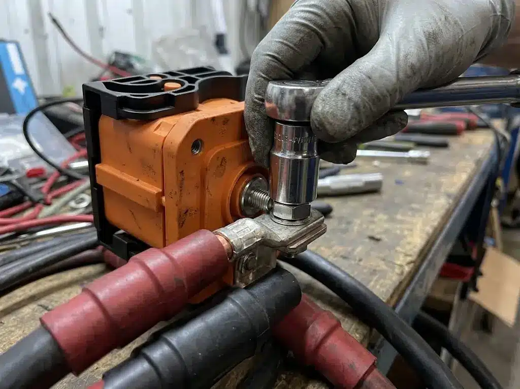
Send the pack voltage window, the converter’s continuous and peak power, the compartment ambient and the cable cross-section. The reply comes back with the frame that covers all four, plus the dimensioned drawing for your panel.
Send your pack figures and cable sizeDivide the continuous battery-side power by the lowest working voltage of the string, then check the result against what is left after temperature derating. On a 250 kW converter the battery side sees about 261 kW, which is 233 A at a 1,120 V floor. That is how to size a manual service disconnect on any pack, and the number changes only when the string or the converter changes.
Continuous current sets the frame, and peak current only changes it when the events repeat often enough to raise the RMS value or last long enough to heat the terminal. A 10 s overload once a day rarely moves the answer. A load-following duty that swings every few minutes usually does.
Use the measured or modeled air temperature at the disconnect location during the hottest hour, not the room temperature. Sealed steel compartments commonly run 15 to 25 K above the surrounding air during a full-power cycle. A part sized from a 25°C datasheet and installed in a 45°C compartment is carrying a load it was never tested at.
It is, with margin, when the string floor is 1,120 V and the compartment stays at 45°C or below. The same frame stops covering the load at around 341 kW on that pack. Converter size, not the part number, is what decides the answer. Ask for the derating curve at your cabinet temperature before the design is signed off.
No. Kilowatt-hours divided by voltage gives amp-hours, which describe duration rather than current. Two packs with the same converter power need the same disconnect regardless of how many hours they run. A 500 kWh pack and a 1,000 kWh pack on the same converter carry identical current.
Not at 416 cells. The charge cut-off reaches 1,518 V, which is above the 1,500 V rating even though the nominal voltage sits lower. Series count and charge cut-off decide this, and both are easy to check before an order is placed. Drop to 400 cells and the same part works with 40 V to spare.

CREEMOS JUNTOS TU SOLUCIÓN DE CONEXIÓN
Indíquenos su aplicación, las especificaciones y la cantidad estimada. Nuestro equipo le recomendará una solución de conectores adecuada y le facilitará un presupuesto.
Pedidos mínimos reducidos · OEM y ODM · Asistencia en la selección de productos · Respuesta rápida a las solicitudes de presupuesto