

¿Necesitas conectores estancos?Solicitar un presupuesto →

An MC4 extension cable exists because the leads on a solar module are never long enough to reach the combiner box. The trouble is that the cable you add becomes part of the circuit. Every extra meter of copper adds resistance, and resistance in a DC string turns into voltage drop, heat, and a permanent loss of yield. No datasheet gives a maximum length, because the limit is not mechanical. The real constraint comes from three things: the conductor cross-section, the current your string actually carries, and the system voltage. Get those right and the extension causes no trouble for the life of the array. Get them wrong and the array underperforms quietly for years without anything visibly broken.
| Término | What it means in practice |
|---|---|
| MC4 extension cable | A two-conductor DC cable with a factory-terminated male and female MC4 connector, used to bridge a gap in a PV string |
| Cross-section (mm²) | The copper area of each conductor. PV cable is commonly 4 mm² or 6 mm² |
| Caída de tensión | The volts lost along the cable at operating current. Expressed as a percentage of system voltage |
| Loop length | Twice the one-way cable length, because current travels out on one conductor and back on the other |
| Mated IP rating | The ingress protection achieved only when the two halves are fully connected. It says nothing about a loose connector |
| Pre-crimped assembly | A cable set terminated and tested at the factory instead of in the field |
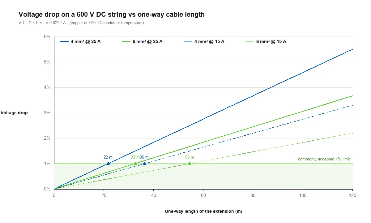
The limit is not mechanical but electrical: how much voltage you are willing to lose. The calculation is short:
VD = 2 × L × I × ρ ÷ A
where VD is voltage drop in volts, L is the one-way length of the extension in meters, I is string current in amps, ρ is the resistivity of copper, and A is the conductor cross-section in mm². Take ρ ≈ 0.022 Ω·mm²/m, which is copper at a conductor temperature near 90 °C. That gives an estimate you can check against your own design.
The table below shows the maximum one-way length of an extension for a given drop budget on a 600 V DC string. These are lengths of the extension itself, not the whole string. For a 1000 V system, multiply by roughly 1.7.
| String current | 4 mm² at 1% | 6 mm² at 1% | 4 mm² at 2% | 6 mm² at 2% |
|---|---|---|---|---|
| 10 A | 55 m | 82 m | 109 m | 164 m |
| 15 A | 36 m | 55 m | 73 m | 109 m |
| 20 A | 27 m | 41 m | 55 m | 82 m |
| 25 A | 22 m | 33 m | 44 m | 66 m |
| 30 A | 18 m | 27 m | 36 m | 55 m |
Read the table as a set of trades rather than fixed limits. Doubling the drop budget or the cross-section doubles the permitted length; doubling the current halves it. Everything is linear, so how far you can reach is really a question about how much loss you will accept.
A worked example: a 20 m extension on 4 mm² carrying 25 A on a 600 V string. VD = 2 × 20 × 25 × 0.022 ÷ 4 = 5.5 V, or 0.92% of system voltage. The same run in 6 mm² drops 3.7 V, about 0.61%. At 25 A the 4 mm² case dissipates roughly 138 W as heat along the cable, against about 92 W in 6 mm². That 46 W gap is lost yield, and the heat raises conductor temperature, which shortens insulation life. For background on how voltage drop behaves in DC circuits, see the caída de tensión reference.
Both sizes carry far more current than a 30 A connector is rated for, so ampacity rarely decides the question. Voltage drop does. The choice usually comes down to run length and climate:
If your calculation lands close to your drop limit on 4 mm², moving up a size is almost always cheaper than discovering the problem after installation. Specifying 6 mm² for an MC4 extension cable that would have worked on 4 mm² costs a little extra copper; discovering the drop problem after the roof is closed costs a second site visit. Note also that conductor resistance rises with temperature, so a string that measures fine on a cool morning can look different at midday in summer. For general conductor sizing background, the solar cable reference covers construction and ratings.
El Conector solar MC4 page lists the specification this article assumes: 30 A, 1000 V, 4 mm² / 6 mm² wiring range, IP68, UL 94 V-2 housing, copper alloy contacts, and CE and RoHS certification. A 1500 V string or a larger conductor needs a different connector rather than an extension.

Once you have settled the length and cross-section of an MC4 extension cable, the remaining decision is where the connectors get terminated.
| Factor | Pre-crimped assembly | Field crimping |
|---|---|---|
| Termination quality | Produced on calibrated tooling, consistent batch to batch | Dependent on the crimp tool, die, and operator technique |
| Field labor | Plug in and route | Strip, crimp, insert contacts, assemble housing, test |
| Length flexibility | Ordered to your specified length | Cut and terminated to any length on site |
| Inspección | Can ship with in-house test records | Verified locally, if at all |
| Ideal para | Repeatable projects, distributor stock, private-label sets | One-off repairs and tight deadlines |
Both approaches work. The failure mode that matters is a crimp that looks acceptable but has insufficient contact area. It passes a quick pull test, then heats up under load. If you crimp on site, use the tool and die specified for the connector, not a generic crimper, and follow the assembly sequence in the MC4 crimping guide. If the volume justifies it, a pre-crimped assembly removes that variability entirely and reduces the number of people who can introduce a defect. It is also why we build pre-crimped sets to length for distributor and private-label programs instead of shipping loose connectors and leaving the termination to the site.
MC4 housings are keyed: a male housing mates only with a female housing. Which housing carries positive depends on the convention used by the module and connector manufacturer, and conventions differ between brands. Do not rely on housing color or on habit.
Every MC4 extension cable you add is another point where polarity can be reversed, and the mistake is invisible from the outside because the housing still mates. The safe procedure is to trace conductors rather than trust appearance:
DC input stages have far less tolerance for reversed polarity than AC equipment, and a mis-wired extension is easy to create when you are adding cable to a run you did not install yourself.
Interoperability between brands. MC4 is a widely used interface, but “fits” and “certified to mate” are different claims. Cross-brand pairs that are not explicitly certified for interoperability can end up with mismatched contact resistance and, under sustained load, thermal failure at the joint. If you cannot confirm the mating pair is certified, use matched connectors. The article on MC4 and PV4 compatibility walks through how to check.
Voltage rating. A 1000 V connector must not be installed in a 1500 V string. The connector rating has to cover the maximum system voltage, not the nominal one.
An IP68 rating is routinely misread as a property of the connector shell. It describes the mated assembly. A connector sitting open on a bench is not watertight, and a pair that is partially engaged is not watertight either. Full engagement is part of the protection rather than a matter of good practice. For context on how the interface is standardized, see the Conector MC4 reference.
If you need repeatable lengths rather than a one-off, an assembly supplier is usually the better route. Pre-crimped MC4 extension cable sets reduce field termination work and improve consistency between installers, and custom cable length, color, and packaging are available for distributor and private-label programs. To quote accurately, a supplier needs: system voltage and maximum string current, conductor cross-section and required length, connector type and pole configuration, quantity, required certification, and any branding or packaging requirement.
If you are still working out which connector family suits the project, the Guía para la selección de conectores solares covers how voltage, current, IP rating, cable compatibility, and installation method fit together. Our control de calidad process covers how crimped assemblies are inspected before shipment.
You cannot confirm an extension was the right call until the string is running. Measure voltage at the array end and at the inverter end at a similar time of day and a similar irradiance level, and compare the difference against the figure you calculated. If the measured drop is meaningfully higher than predicted, the most likely causes are an undersized conductor, a high-resistance crimp, or a partly engaged connector. All three are cheaper to correct early. If you would like the calculation checked against your project design, solicitar un presupuesto and include the string data.
Practical answers about MC4 extension cables, cable sizing, voltage drop, and connector compatibility.
There is no universal maximum. On a 600 V string at 25 A, a 4 mm² extension stays under 1% voltage drop up to about 22 m of cable, and 6 mm² reaches about 33 m. At 1000 V those lengths increase by roughly 1.7 times. The limit is your acceptable voltage drop, not a product restriction.
Use cable specified for outdoor DC PV use. It has UV-resistant insulation and a temperature rating suited to continuous outdoor exposure and to the heat generated at the conductor. General-purpose building cable is not a substitute, and local code may specify requirements in any case.
You can, but it adds a mated pair and more resistance. One correctly sized cable is better than two short ones, both electrically and in terms of failure points. If you must join, verify that the connection is fully engaged and that the mating pair is certified for interoperability.
It reduces array voltage at the inverter, which reduces power slightly. At 1% voltage drop the loss is around 1%, which is usually acceptable. Larger drops cost proportionally more, and the same resistance also generates heat along the cable.
Only if the specific pair is certified for interoperability. Otherwise use matched connectors from one manufacturer. The risk of an uncertified pairing is mismatched contact resistance and thermal failure at the joint under sustained current.
The connector rating does not set the cable size. Choose the cross-section from your voltage-drop calculation and the string current, then confirm the connector accepts that conductor. A 4 mm² or 6 mm² range covers most residential and commercial extensions.
Send us your system voltage, string current, cable size, required length, and quantity, and we will confirm the connector and conductor combination, quote the assembly, and arrange samples for engineering evaluation.

CREEMOS JUNTOS TU SOLUCIÓN DE CONEXIÓN
Indíquenos su aplicación, las especificaciones y la cantidad estimada. Nuestro equipo le recomendará una solución de conectores adecuada y le facilitará un presupuesto.
Pedidos mínimos reducidos · OEM y ODM · Asistencia en la selección de productos · Respuesta rápida a las solicitudes de presupuesto