

Precisa de conectores à prova d'água?Solicite um orçamento →
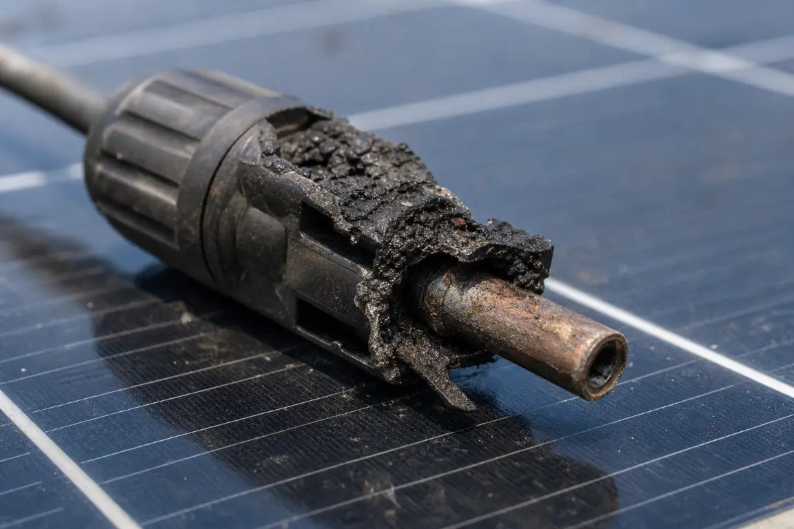
A melted solar connector is the end of a process, not a sudden event. Most solar connector overheating starts at one of two interfaces: the cable-to-terminal crimp, or the mated contact pair. When resistance at either interface rises, the joint turns current into heat. The housing is usually the last part to fail.
Principais conclusões
- Two interfaces cause almost every overheating failure: the crimp and the mating pair.
- The most common root cause is a termination that was never made to the connector’s own assembly specification.
- Heat raises resistance, and resistance raises heat. A joint that is running hot will not settle down on its own.
- A visual symptom does not identify a cause. Records, thermal imaging, resistance measurement and a pull test answer different questions.
- Replace damaged parts only after the cause is identified. Otherwise the failure returns at the same position.
The useful question is not “which connector should be replaced”. It is “what made this connection overheat”. Damaged plastic is evidence, not the fault. Leave the assembly, compatibility or cable-management problem in place, and a new connector pair will fail the same way at the same position.
Nota de segurança: PV DC circuits remain energized in daylight, and most PV connectors are not load-break devices. Do not disconnect, open, probe or repair a connector under load. Inspection and corrective work belong to qualified personnel, working to the connector manufacturer’s instructions and the electrical code adopted at the site.
| Possível causa | Pistas típicas |
Como um técnico qualificado verifica isso |
Direção corretiva |
|---|---|---|---|
| Crimpagem ou montagem do terminal incorreta | Aquecimento próximo à entrada do cabo; terminal descolorido; fios soltos ou danificados | Verifica o tamanho do condutor, o comprimento do fio descascado, a posição do terminal, a geometria da crimpagem e a montagem, comparando-os com as instruções do fabricante | Substitua o conjunto danificado e refaça-o utilizando o cabo, o terminal, a matriz e a ferramenta especificados |
| Marcas ou modelos de conectores incompatíveis | Marcações ou fabricantes diferentes nas duas metades de encaixe; interface de encaixe a quente | Identifica os números de peça dos conectores e verifica a compatibilidade documentada ou a inclusão na lista | Substitua por uma combinação de acoplamento aprovada e documentada |
| Acasalamento incompleto | As abas de travamento não estão totalmente encaixadas; há uma folga visível; aquecimento localizado na interface | Inspeciona o encaixe e verifica a montagem utilizando o método prescrito pelo fabricante | Desligue a alimentação e substitua quaisquer peças danificadas; reconecte de acordo com as instruções |
| Umidade, sujeira ou corrosão | Corrosão, resíduos, carcaça rachada, vedação danificada, ou histórico de conectores sem tampa | Inspeciona todo o sistema de vedação, o encaixe dos cabos, o invólucro e os contatos após o isolamento de segurança | Substitua os componentes afetados e corrija o problema de vedação ou de instalação |
| Cabo, conector ou aplicação de corrente/temperatura incorretos | Aquecimento na extremidade; diâmetro incorreto do cabo ou seção transversal incorreta do condutor; conexão de ramificação sobrecarregada | Compara os números de peça exatos, o tamanho do condutor, o diâmetro do cabo, a corrente, a temperatura ambiente e os dados de redução de potência | Escolha um sistema de cabos e conectores compatível com parâmetros adequados |
| Desconexão sob carga | Marcas de arco elétrico, corrosão por pite, fuligem ou danos após a manutenção | Analisa o histórico de manutenção e examina as superfícies de contato após o isolamento seguro | Substitua os componentes danificados pelo arco elétrico e corrija o procedimento de isolamento |
| Tensão mecânica ou má organização dos cabos | Conector pendurado pelo cabo; curva acentuada próxima ao prensa-cabos; movimento, tensão ou carcaça amassada | Verifica o suporte, o raio de curvatura, o alívio de tensão, o traçado e o movimento | Substitua as peças danificadas e fixe o conector sem exercer pressão sobre a interface de acoplamento |
| Peças danificadas, envelhecidas, falsificadas ou fora de conformidade | Rachaduras, deformações, ausência de marcas de certificação, marcações inconsistentes ou origem incerta | Confirma a rastreabilidade, a certificação, os números de peça e o estado | Utilize componentes rastreáveis e certificados, provenientes de uma fonte autorizada |
Most solar connector overheating arguments at site level are about thresholds, not physics. Three measurements separate a healthy joint from a failing one.
Two standards frame those numbers. IEC 62852:2014+A1:2020 covers PV DC connectors up to 1500 V DC and 125 A per contact. It classes them as connectors without breaking capacity that may still be engaged and disengaged under voltage. In the United States, NEC 690.33(C) requires both halves of a mating pair to be the same type and brand, or listed as intermatable.
Treat every threshold as model-specific. Usable current depends on conductor size, cable construction, ambient temperature and the derating published for that exact part number.
Solar connector overheating begins with resistance. Every conductive joint has some, and current through it dissipates power as heat according to P = I²R. The behavior is not linear in practice. As the joint warms, its resistance increases, which produces more heat. A modest contact problem can move from warm to damaged faster than the string current suggests, because current barely changes while the joint fails.
Contact resistance has two parts. Bulk resistance is the material itself. Constriction resistance is current squeezing through the small areas where two metal surfaces actually touch. Crimp pressure, contact spring force and surface condition set how large those areas are. That is why a loose joint and a corroded joint can behave the same way electrically.
Overcurrent protection is sized for the circuit, not for one joint. A string at its normal current can carry a joint dissipating tens of watts in a spot a few millimeters across. The breaker sees nothing unusual. That case, and what failure marks on a housing tell you, is covered in our breakdown of a melted MC4 connector that kept the system running.
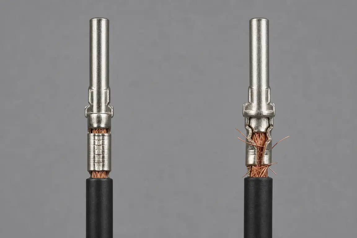
The cable-to-terminal crimp is the most heavily loaded interface in a PV connector. It fails in predictable ways. The conductor is not inserted to the required depth. The strip length is wrong. Strands are cut or missing. The terminal does not match the conductor size. An unapproved tool or die closes the barrel.
Every one of those defects cuts the metal-to-metal contact area, and less contact area means more resistance at the same current. The damage then compounds: thermal cycling works the strands loose, movement opens the joint slightly, and resistance creeps up over the string’s life. In field investigations the crimp is usually the one interface never checked against the connector’s own assembly specification.
Prevenção: Follow the assembly instructions for the exact part number. Use the specified cable, terminal, strip length, tool and die, then complete the manufacturer’s dimensional and engagement checks. Factory-assembled leads remove that field variability, but they still need correct integration. Our comparison of crimped and soldered terminals covers what each method does to the conductor; the crimping walkthrough covers tool, die and strip length.
Two PV connectors can latch together and still be a poor electrical pair. Contact geometry, contact force, tolerance stack-up, sealing and materials differ between families. A pair that was never qualified together can develop a smaller contact area, a weaker seal, or both.
In the United States, NEC 690.33(C) requires connectors of different types or brands to be listed and identified for intermatability as described in the manufacturer’s instructions. Local requirements depend on the code edition the authority has adopted. Most cross-mating on site happens between two families that look alike and are both sold as “MC4 compatible”. That is a market phrase, not an electrical statement.
Prevenção: Record the manufacturer and complete part number of both halves. Use one approved connector system unless a specific cross-brand combination is documented as intermatable. If one half is unknown, treat the pair as unmatched. Our MC4 and PV4 connector differences note is the quick check, and approved halves are listed on the PV4-style solar connector page.
A connector that is not fully engaged can look connected while the locking mechanism is not seated. The contact area at the pin-and-socket interface is then smaller than designed, and less stable under load. Movement wears the plating, fretting corrosion follows, and resistance climbs from there.
The causes are mundane. A latch never clicked. Contamination sits in the coupling. The installation was made in poor light with gloves on. A locking feature was already damaged by an earlier event. The failure is silent at first, and it shows up later as one hot connector at the end of a string.
Prevenção: Mate exactly as the product instructions describe, and perform the prescribed engagement check instead of judging by feel. Do not force together parts that do not mate normally. Where a connector has already overheated, arced, deformed or lost locking integrity, replace the affected components. Do not push the halves back together and return the string to service.
An IP rating applies only when the correct components are assembled, mated and used with a compatible cable. Water and contaminants enter through a damaged housing, a cable outside its specified diameter range, a compromised seal, poor assembly, or an unmated connector left exposed without its cap. Once moisture reaches the contact or the crimp, corrosion reduces the real contact area while the sealing system degrades at the same time.
Visible corrosion also warns about scope. A corroded joint has usually been running hot, and that heat may have damaged the terminal, the strands and the insulation inside the housing.
Prevenção: Keep unmated connectors clean, dry and capped with approved sealing caps. Replace contaminated, corroded, cracked or heat-damaged components. Do not apply grease, cleaner or sealant unless the manufacturer approves it for that product. On coastal, agricultural or washdown sites, exposure belongs in the replacement decision too: the IP67 versus IP68 comparison shows what each rating covers when a joint is mated, and when it is not.
A connector’s usable current is not one universal number. It depends on the connector model, conductor cross-section, cable construction, ambient temperature, certification basis, installation conditions and the derating the manufacturer publishes. A generic “30 A MC4” assumption is not a design input.
Both cable characteristics matter, for different reasons. The conductor cross-section drives electrical and thermal performance. The outside diameter decides whether the gland seals and whether the strain relief grips. A package that satisfies one and not the other produces either a hot joint or a wet joint. System changes follow the same logic. Adding modules in series raises voltage. Paralleling strings raises current in shared conductors and branch connections.
Prevenção: Confirm the connector part number, the compatible cable type and diameter, the conductor size, the maximum circuit current, the ambient limits and the published derating, not the headline rating. The datasheet and the crimp-tool specification settle most of it; both are in our connector datasheets and drawings section. If you are still comparing families, the guia de seleção de conectores solares sets out the trade-offs.
Most PV connectors carry a “Do Not Disconnect Under Load” marking. IEC 62852 describes this class of connector as having no breaking capacity while still being capable of engagement and disengagement under voltage. Separating a pair while current flows draws a DC arc. Unlike an AC arc, it does not self-extinguish at a current zero. It can pit and erode the contacts, deposit conductive residue, and damage the housing.
The fault is created during maintenance, not installation. It follows a string that was isolated by switching something off instead of by verifying zero current at the connector.
Prevenção: Use the site’s approved isolation procedure and confirm that no load current is flowing before separating a connector that is not rated for it. Replace components that show evidence of arcing or thermal damage, including the mating half that looks undamaged.
The electrical contact should not support the cable. A connector left hanging, pulled sideways, bent sharply at the gland, crushed by a cable tie or moved repeatedly loads the seal, the crimp and the mating interface at once. Movement is worse than static load, because it works the joint open in small increments and the damage stays invisible until resistance rises.
Tracker installations, wind, thermal expansion and routine maintenance all move cables. On a tracker the connector sees cycles every day rather than once a season.
Prevenção: Support and route cables so the connector is not under tension, torsion, bending load, impact or repeated movement. Follow the manufacturer’s bend-radius, support and strain-relief requirements. Keep connectors clear of standing water and abrasive surfaces.
UV exposure, high ambient temperature, chemicals, impact, animals and earlier overheating all weaken housings and seals. Counterfeit and untraceable products are a separate problem. They may not match the construction, materials, tolerances or certification behind the markings they imitate, and the marking is not evidence of anything.
Age alone does not set a replacement interval. A connector in its tenth year can be in better condition than one installed two years ago on a badly managed tracker. Condition, environment, installation quality and inspection findings decide the answer, not the calendar.
Prevenção: Buy traceable components from authorized sources and keep product and installation records. During scheduled maintenance, look for cracks, discoloration, deformation, damaged latches, poor support, corrosion and inconsistent markings. Our processo de controle de qualidade describes the checks a connector goes through before shipping, which is the record you should be able to ask any supplier for.
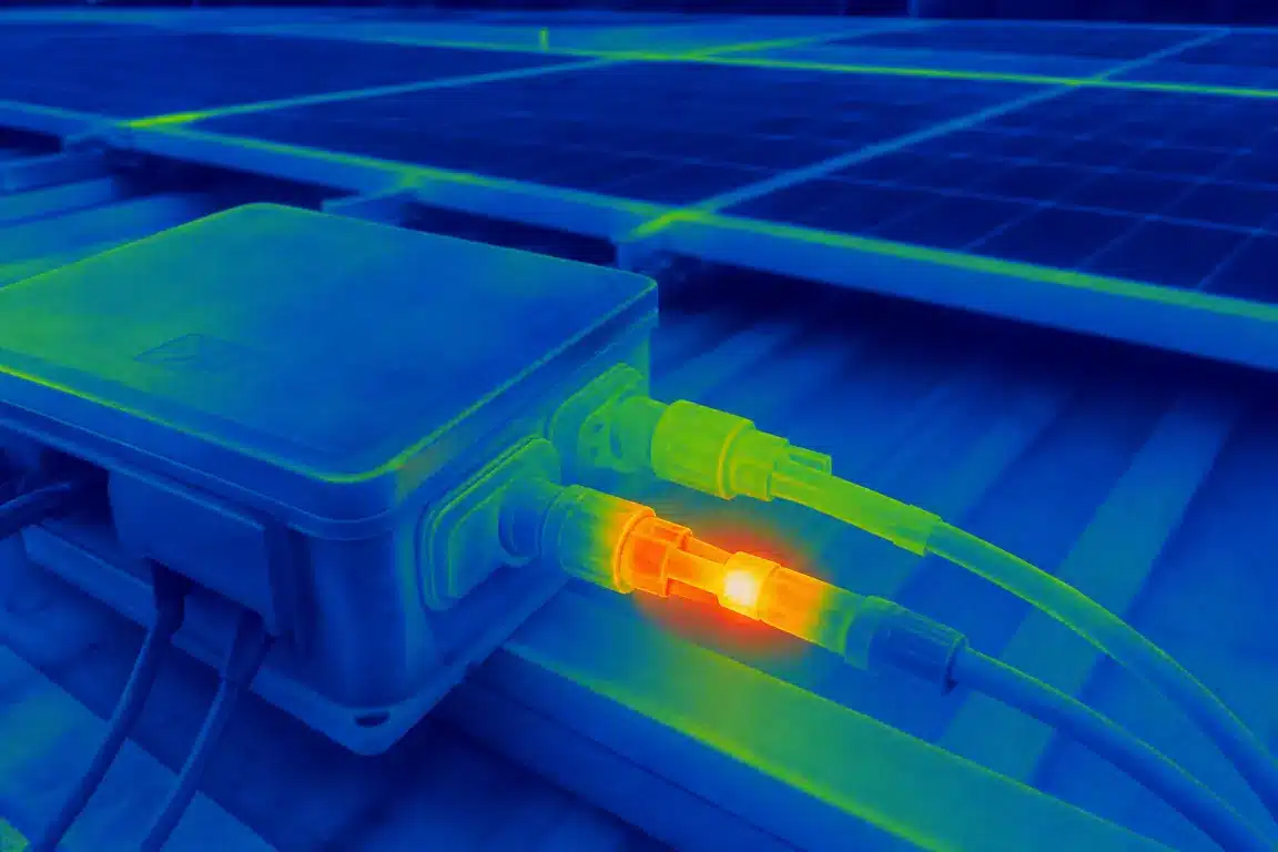
Como detectar com segurança um conector superaquecido
Detecting solar connector overheating early costs far less than replacing a failed string section. Work in this order.
Review alarms, production data and maintenance history first. Then inspect visually for discoloration, deformation, cracks, corrosion, loose support and mismatched markings. Use non-contact thermal imaging under suitable operating conditions.
Continue with electrical testing and disconnection only after an approved shutdown and isolation. Do not use a bare-hand touch test to judge whether a connector is safe, and do not disconnect a PV connector simply to find out whether it is hot.
If the cause is still not obvious after the visual check, the field sequence (pull test, resistance measurement, thermography) is set out step by step in our MC4 failure diagnosis checklist.
Infrared thermography shows a temperature difference. It does not name a cause. A single reading without a comparison is meaningless, because current, shade, wind and mounting all change surface temperature. The useful method is to compare connectors carrying similar current under similar conditions. Confirm any suspect joint with a resistance or pull test once the string is isolated.Do not use a bare-hand touch test to judge connector safety, and do not disconnect a PV connector merely to “see whether it is hot.”
Practical answers to common questions about solar connector temperature, damaged joints, compatibility, current ratings and inspection intervals.
Warm is normal, and solar connector overheating is not measured by touch. Connector temperature depends on current, ambient temperature, cable size, installation conditions and product limits. Compare equivalent connections with thermal equipment, then evaluate the result against the manufacturer’s data for that part number.
Not until the underlying cause has been identified. Heat and arcing can damage the mating half, cable, terminal or nearby insulation even when the damage is not obvious from the outside. A qualified technician should determine the replacement scope, remake the connection with approved components, and record what was found.
No. Physical fit does not prove electrical compatibility, certification or code compliance. Two housings can latch while contact geometry, spring force and sealing differ. Verify the exact manufacturer, model, listing and documented intermatability of both halves, and keep a written record of the pair so the next technician is not guessing.
Reverse polarity can damage or prevent the operation of connected equipment, but current flowing in the opposite direction does not inherently increase the connector’s contact resistance. Treat it as a separate wiring and equipment-protection fault, and correct it on its own terms.
No. A larger connector does not repair a poor crimp, a partly seated pair or water in the housing, and it does not change the current the string carries. Higher ratings widen the margin against ambient heat and derating. Confirm the cause first, because a joint with high resistance will run hot whatever the rating says.
There is no universal five-year rule for every product and installation. Use the manufacturer’s guidance, the site maintenance plan, applicable codes, environmental exposure, system criticality and previous inspection findings to set the interval, then review it after any string-level fault or thermal event.
Send us your application, cable size and required quantity. Our team can help confirm a suitable connector configuration and provide a quote.

VAMOS CRIAR SUA SOLUÇÃO DE CONECTIVIDADE
Envie-nos sua aplicação, especificações e quantidade estimada. Nossa equipe recomendará uma solução de conectores adequada e fornecerá um orçamento.
Baixo MOQ · OEM e ODM · Suporte na seleção de produtos · Resposta rápida à solicitação de cotação