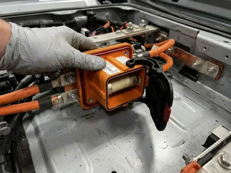


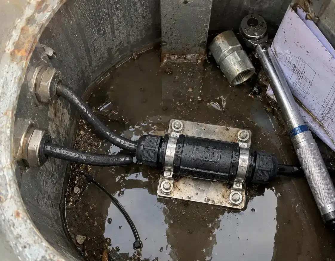
A lighting connector for an industrial lighting project is chosen from the circuit it joins, not from the luminaire at the far end of it, and that is why one pole can carry three different parts. A feeder enters the handhole at one voltage and one pole count. The branch to the fixture adds a control conductor. The driver output runs at a different voltage class altogether. Write all three down as “waterproof connector, IP68” and the quotation comes back with a part that fits none of them properly. What follows is the set of joints a plant lighting job actually has, the four numbers that fix each part, and a block of text a supplier can quote from without a second call.
It carries current, keeps water out of the joint, and comes apart when a fixture is serviced. Those three duties are set by where the joint sits, so naming the joint matters more than naming a series. A luminaire disconnect at the fixture door and a feeder joint sitting in standing water are two different products against the same luminaire.
Most plant lighting drawings show six joints, and they are rarely served by the same lighting connector.
| Connection point | What it joins | Voltage and poles to state | Sealing normally asked for | What buyers leave out |
|---|---|---|---|---|
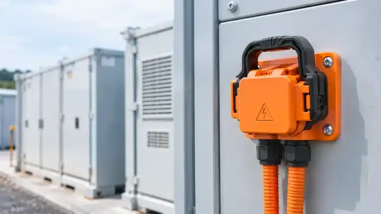
| Handhole, feeder to branch | Main run and the branch to each pole | 277, 347 or 480Y/277 V AC, 2 to 4 poles including PE | IP68, joint sits below the cable entry | How deep the water stands in the handhole |
| Branch to luminaire lead | Branch cable and the fixture lead | System voltage, 2 or 3 poles with PE | IP68, UV-stable jacket | Whether the lead arrives factory-terminated |
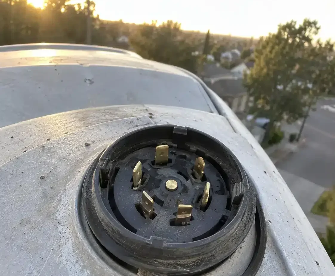
| Photocontrol or dimming base | Control device and the driver | AC supply plus a low-voltage control circuit, seven contacts | IP66 or IP68 with a gasket | Which control interface the driver expects |
| Driver output to LED module | Driver and the LED board | DC output class from the driver label, 2 to 6 poles | IP67 inside the housing | Current, because the label shows watts |
| In-grade or landscape run | Buried cable and the fixture | AC, sometimes DC, 2 or 3 poles | IP68 plus a burial rating | Burial depth and soil water level |
| Panel or branch box to circuit | Distribution board and the outgoing run | AC line side, 3 or 4 poles with PE | Gland and enclosure rating, not a connector rating | The lug range the breaker accepts |
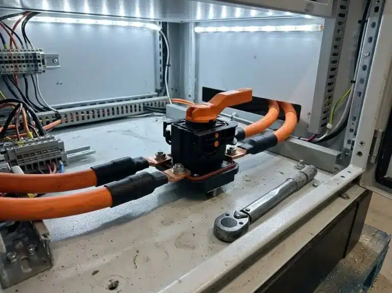
Two of those rows cause nearly all the rework. The first is the handhole, where a lighting connector rated IP68 can still sit in water for a week after a storm and be asked to hold that condition. The second is the control base, because a seven-contact receptacle and a two-wire dimming pair are not interchangeable and the difference is invisible on a one-line diagram.
Buyers arrive at a lighting project with photovoltaic habits, which is reasonable given how much of the work sits in the same buildings. The parameters that come across the desk look like this: 1,500 V DC, 30 A, MC4-compatible. None of it survives contact with a lighting circuit. Industrial lighting runs on alternating current, and the lighting connector is selected against a system voltage rather than against a module current.
Voltage on a lighting drawing is a system figure before it is a device figure. The calculation voltages come from a fixed list in NFPA 70: 208Y/120, 480Y/277 and 600Y/347 are three of them. The number on the drawing is one of those, rather than whatever the fixture nameplate happens to print. A 480Y/277 V branch puts 277 V from line to neutral at the joint. Canadian plants in the same program often run 600Y/347, which moves the same joint to 347 V.
Before any current figure arrives, the system voltage has already narrowed the lighting connector to a family. A connector rated for 600 V is a device rating, and it says nothing about which system it should be installed on. Put a 347 V joint on a part whose documentation stops at 300 V and the certificate no longer covers the installation, however well the contacts carry the load.
Pole count on a lighting connector follows the same logic, and it is where drawings most often go quiet. A single-phase branch with a protective earth needs three poles. A three-phase four-wire branch with earth needs five. Photocontrol and dimming circuits add control contacts that are not power poles at all, and mixing the two counts produces a housing that is either too small or has cavities nobody will terminate.
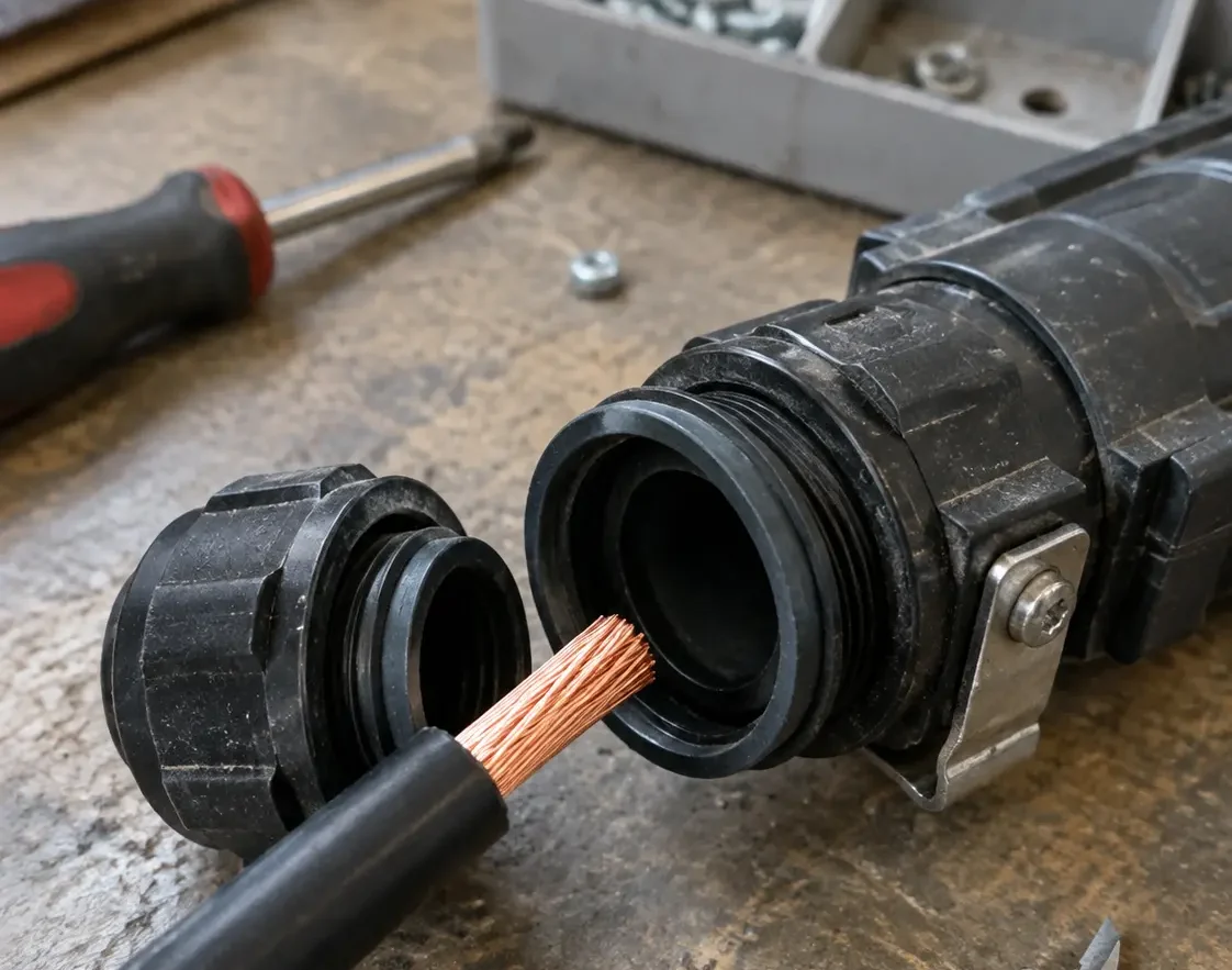
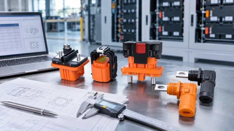
Four figures settle the selection of an industrial lighting connector at any one of the six joints, and each of them changes something different downstream. Get them in the first message and the quotation is a specification match. Leave any of them out and the supplier guesses, usually toward a larger housing.
| Number | What it fixes | What buyers send instead | What it changes downstream |
|---|---|---|---|
| System voltage and current type | Insulation, creepage and the certification range | The fixture wattage | Which product families are allowed at all |
| Branch circuit current | Terminal size, conductor range and heat at the contact | The lamp wattage divided by 230 | Whether a 4 mm² conductor fits the gland |
| Pole count including protective earth | Housing size, keying and the number of cavities | A count of fixture wires | Handhole space and the risk of a mis-mated pair |
| Installation location and water exposure | Seal design, housing material and UV stability | The words “it gets wet” | Whether a gasketed shell is enough or a potted one is needed |
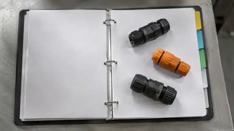
A lighting branch is loaded continuously for most of the night, and the branch protection is sized with an allowance above the running current. The lighting connector has to live with the conductor that allowance produces, not with the wattage printed on the fixture label. Ask what conductor the electrician will pull, and give that number. The screw-type waterproof range is rated 17.5 A to 32 A at 450 V AC, which covers a single-fixture branch. That lighting connector rating only holds inside its stated conductor range, 0.5 to 1.5 mm² on the 17.5 A models, so the cable belongs next to it in the inquiry.
Most of this text can be written once and reused. Five circuit types cover industrial lighting work, and each one has a line of text that belongs in the inquiry. Writing them out takes two minutes and removes the usual round of questions.
| Circuit on the drawing | Conductors at the joint | The line that belongs in the inquiry |
|---|---|---|
| 277 V single phase from a 480Y/277 source | Line, neutral, PE | 277 V AC, 3 poles including PE, wet location |
| 480 V three phase, four wire | Three lines, neutral, PE | 480 V AC, 5 poles including PE, handhole |
| 347 V single phase from a 600Y/347 source | Line, neutral, PE | 347 V AC, 3 poles including PE, Canadian project |
| Driver output, Class 2 | Positive and negative | DC output class, 2 poles, inside the housing |
| Photocontrol or dimming base | Seven contacts | Photocontrol receptacle to ANSI C136.41, protocol named |
Describe the photocontrol receptacle in full, because it is the one lighting connector with a standard written around it. ANSI C136.41 covers the dimming interface between an external locking-type control and a driver, and the receptacle carries seven contacts: three for line, neutral and load, with the remainder for dimming and auxiliary signals. State the protocol the driver expects, because a 0-10 V pair and a digital addressable pair do not share a wiring convention. A waterproof connector for LED lighting that has to pass control signals is a different product family from one that only passes 277 V.
An IP68 marking is two digits and a test condition, and the condition is what the lighting connector will actually see. Immersion depth and duration belong in the specification, not in a footnote. Our own IP68 range carries a 2 m, 120-hour immersion figure, which is a defensible figure for a handhole that fills after rain and not a claim about permanent submersion.
Where the joint sits decides which number matters on the part itself. A pole handhole at a kerb line collects road spray and stands in water for days, which is what pushed one municipal program toward a three-layer connector layout on a smart pole. An in-grade fixture sits under whatever the drainage does. A wash-down bay in a food plant uses pressure that IP68 does not describe at all, and that is a separate test. Coastal sites add salt, which attacks the plating before it attacks the seal.
Once the location is fixed, the housing material is the next decision, and it is the one made last. A lighting connector that will be re-entered twice a year needs a gasket that survives being opened, and the same joint in a sealed driver housing does not. The difference between IP68 and IP69K washdown ratings explains why the higher number is not automatically the safer choice for a lighting joint.
Paste these six lines into the first message. Anything shorter comes back as a quotation with assumptions attached, and assumptions are what a second round is made of.
For the wider set of parameters that applies to any lighting connector order, the connector RFQ checklist already covers packaging, quantities and acceptance tests. What is left here is the six lines a lighting connector inquiry cannot do without, which is exactly the part a lighting project gets wrong.
Three errors account for most of the lighting connector re-quotes we see on lighting programs, and all three are cheap to prevent at the drawing stage.
| What the inquiry says | What the supplier has to assume | What it costs | How to write it instead |
|---|---|---|---|
| “IP68 connector, 3 pin” | A lighting connector for a 300 V class joint | A certificate that does not cover the installation | State the system voltage and the pole count separately |
| Watts per fixture, no conductor size | The smallest terminal in the family | A gland that will not take the pulled cable | Give the conductor cross-section the crew will install |
| “Outdoor, gets wet” | A gasketed shell with no immersion rating | Water in the joint after the first storm | Name the location and the depth it stands in |
Read the three rows again and the pattern repeats on every lighting connector inquiry: a product word replaces a circuit fact, and the supplier fills the gap with something reasonable. What arrives then looks correct on the packing list and fails in the handhole.
A street light connector program we shipped in 2025 is a fair illustration of how the detail pays off. The specification that worked was not longer than the one that failed. It simply named the water condition in the handhole and the conductor the crews were pulling, which is what let the sealing system and the terminal range be chosen together rather than in sequence.
Send the joint, the system voltage and the conductor size, and what returns is a part, a drawing and a test report that match the circuit rather than the product name.
Technical guidance for street lighting connectors, LED luminaire connections, waterproof protection and electrical project specifications.
Write the system voltage and the joint voltage, because they are not the same line. A 480Y/277 V source delivers 277 V from line to neutral at a single-phase lighting joint, so the inquiry should read 277 V AC with 3 poles including PE. Sending 480 V alone invites a lighting connector rated for the higher figure, which usually means a larger housing in a small handhole.
Usually yes. The driver output is a DC circuit at a low voltage class, it sits inside the luminaire housing, and it carries a current that the fixture label hides behind a wattage. A waterproof connector for LED lighting on that side is selected on current and on fit inside the housing, while the lighting connector at the fixture entry is selected on system voltage and poles.
It can, and often does, when both joints carry the same voltage and the same pole count. The reason to keep two lighting connectors is mechanical rather than electrical. A handhole joint sits in standing water and gets re-entered for testing, while the luminaire disconnect is opened when the fixture is replaced. The two joints see different service life, and the gasket duty on a lighting connector follows.
It depends on the depth and the time, and neither is in the two digits. IP68 is a manufacturer-declared immersion condition for a lighting connector, so the depth and duration have to be written into the specification and matched against the test report. Our own figure is 2 m for 120 hours. A lighting connector that sits in a flooded handhole for a week is being asked for something else.
The certificate set for a lighting connector follows the target market, so name the market in the inquiry. United States roadway and area lighting projects work to ANSI C136 series requirements for luminaires and controls, and component connectors are recognized under UL 1977. European projects need the declaration of conformity and the test reports behind it. Our certificates page sets out what each document covers, and each report is issued for one model and one market.
Enough lighting connectors to cover the largest joint count on one pole multiplied by the poles in the first phase. Lighting programs rarely order one pole at a time, and a quantity tied to the drawing lets the supplier quote tooling and lead time honestly. A sample of each joint type before the bulk order settles the fit questions that photographs cannot.

LET’S BUILD YOUR CONNECTION SOLUTION
Share your application, specifications, and estimated quantity. Our team will recommend a suitable connector solution and provide a quotation.
Low MOQ · OEM & ODM · Product Selection Support · Fast Quote Response