

Need waterproof connectors?Request a Quote →
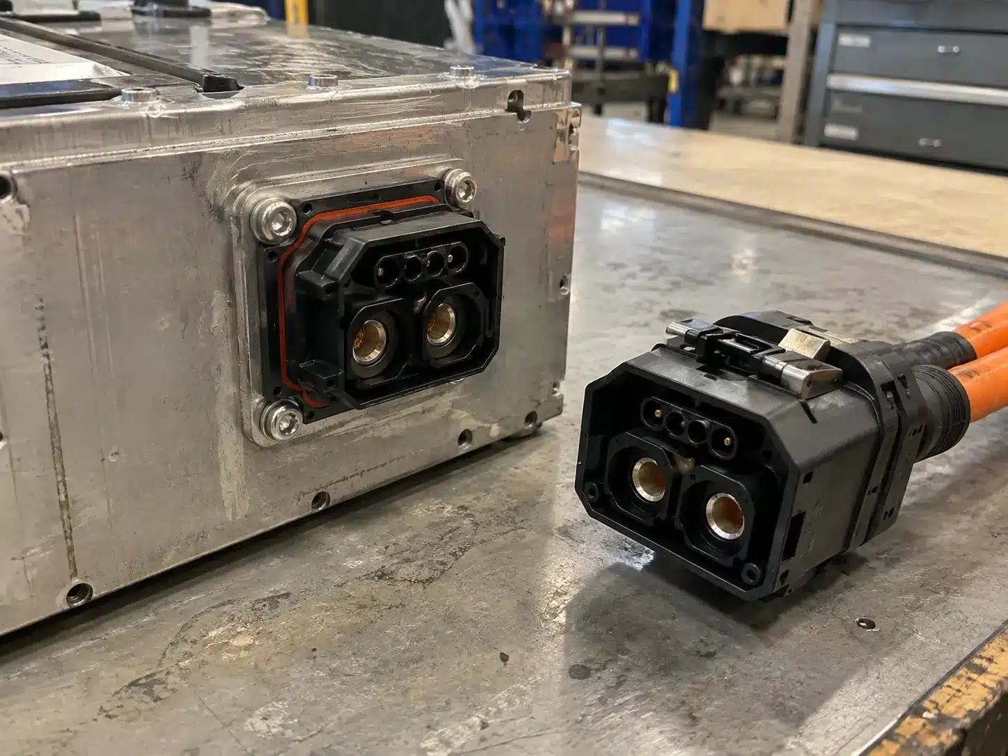
A stackable battery connector joins modules bolted one on top of another, and the contacts inside those housings are either floating or fixed. A floating contact sits in a block that can move a short distance as the halves come together, so the stackable battery connector absorbs the alignment error that grows with every module added to the stack. A fixed contact is locked to the housing, which keeps the current path rigid and hands the alignment work to the frame and the assembly crew. Three inputs decide which one your stack needs: the number of modules, how they are guided into position, and how often the joint is unmated.
| Item | Detail |
|---|---|
| Stackable battery connector, floating version | 50A to 70A, 220V DC, gold-plated brass contacts, ≤0.5mΩ contact resistance, M4 fixing, -40°C to +125°C, UL94 V-0 housing |
| Stackable battery connector, fixed version | 120A to 240A, 1500V DC, silver-plated copper contacts, ≤0.5mΩ contact resistance, M4 fixing, -40°C to +125°C, IP67 on the mated pair |
| Mounting panel, floating version | 3.0 mm thick, panel tolerance ±0.05 |
| Float range | Not set by any standard. The figure comes from the connector supplier |
| What sealing is measured against | IEC 60529, with depth and duration declared by the manufacturer |
| Rule that applies to both designs | Never mate or unmate under load. Isolate the DC string and prove no voltage first |
Floating is not the same as spring-loaded. A spring contact is a single piece that flexes to hold pressure on the mating surface. Floating means the whole contact block travels as a unit inside the housing, usually in the plane of the mating face and sometimes with a few degrees of angular freedom. A lead-in chamfer or a guide on the mating half pushes that block into line as the plug goes in, which matters most on a blind mate where nobody watches the interface during assembly. A fixed contact has no such mechanism. Its position comes from the moulding, the panel and the screws holding the housing down, so the accuracy of the finished joint is the accuracy of everything made before it.
[Image 2, real photo required: close macro of the contact block inside the floating housing, showing how the block sits in its travel and the lead-in faces around it, shallow depth of field]Alt: Floating contact block inside a stackable battery connector housing, showing the travel available around the contacts
| Term you will see | What it fixes on a drawing or a datasheet |
|---|---|
| Floating contact, floating block | A contact assembly with a controlled range of movement inside the housing |
| Fixed contact, also written stationary | A contact locked in the housing, positioned by the moulding and the panel |
| Float range | How far the floating part of a stackable battery connector travels. A supplier figure, not a standard value |
| Self-alignment | Lead-in surfaces and float working together to bring the halves into line |
| Tolerance stack-up | The sum of the permitted errors from module, frame, panel and connector |
| Blind mate | Mating that cannot be watched during assembly |
| Wiping | A slight slide of the contact surfaces during mating that works through surface film |
The wording is loose in the trade. Suppliers use floating for a moving contact block, and also for a float-mount fixing where the whole housing moves on its fasteners. Both exist; they solve different problems, and a quote that does not say which one is on offer cannot be checked against a drawing.
Alignment error at one interface is rarely the issue. Interfaces add. In a stack of four modules, with each interface allowed ±0.5 mm in the plane of the panel, the fourth module can sit 2 mm from where the first one sits, because nothing forces those errors to point in opposite directions. A root-sum-square calculation on the same numbers gives about 1 mm, the figure that usually appears in documents. A design that only works at that figure will still fail on the first build where the tolerances line up, so the tolerance block on your own drawings is the one that counts.
[Image 3, deliver as the attached PNG or redraw in Canva: four stacked module outlines with the interface offset marked at each level, worst case 2 mm at the top against a root-sum-square figure of about 1 mm, no invented tolerances beyond the example]Alt: Tolerance stack-up across four stacked battery modules: worst case 2 mm against a root-sum-square figure of about 1 mm
A stackable battery connector with a floating contact absorbs that sum at the contact, the last place the error appears. A fixed contact passes it into the structure, where the frame, the panel hole and the jig have to hold the position instead. Neither approach removes the error, so the choice is where you want it to land.
On a battery stack the errors come from four places: the module moulding, the frame carrying it, the panel the stackable battery connector is bolted to, and the tolerance on the panel cut. In the floating version of our 70A model, the panel tolerance is ±0.05 mm on a 3.0 mm panel, and stacking multiplies it anyway. Float covers the gap between the drawing and the module that arrives.
What it costs is a mechanism. The block has to keep normal force on the mating surface across its whole travel, so the spring element behind it both holds contact pressure and allows movement. Anything that restricts that travel removes the margin the design was built around, whether a cable pulls sideways on the housing, a fastener goes down before the block is centred, or the stack sits at one end of its range. A stackable battery connector that has used up all of its float behaves like a fixed contact with a longer current path.
A fixed contact gives a short, stiff current path and a contact position that does not change over the life of the assembly. There is no moving block to wear and nothing to re-centre after service, which is why the higher current class in this range is built that way: 120A to 240A at 1500V DC, silver-plated copper contacts, IP67 on the mated pair, UL94 V-0 housing.
[Image 4, deliver as the attached PNG or redraw in Canva: two-panel line drawing, left panel a floating contact block with travel arrows, right panel a fixed contact locked to the housing, labels in one language]Alt: Floating contact block with travel against a fixed contact locked to the housing in a stackable battery connector
The demand it puts back is on the assembly. If a module does not arrive where the frame said it would, a fixed contact cannot close the gap, and the part takes the misalignment as side load. A stackable battery connector drawn together with the halves out of line loads its contact beams unevenly. Drawings cover part of this with guide features or a locating step on the panel. The rest happens on the line: bring the module in on its rails, seat it by hand, and let the fasteners clamp rather than align.
[Image 5, real photo required: the 240A fixed stackable connector bolted to a cabinet floor, cable landed on the terminals, torque wrench in frame, cabinet interior lighting]Alt: Fixed stackable battery connector bolted to a cabinet floor with the cable landed on the terminals
| Your situation | Better fit | Why |
|---|---|---|
| Three or more modules, assembled by hand | Floating | Stack-up grows with the module count, and the stackable battery connector absorbs it instead of the frame |
| Modules slide into a cabinet or rack, so mating is blind | Floating | Lead-in and float correct in-plane error in one movement |
| A 1500V DC string in the 120A to 240A band | Fixed | The higher current and voltage class sits in the fixed version |
| Frame is machined and the assembly is jigged | Fixed | Position is already controlled, so float adds a mechanism with no job to do |
| The connection lands on a busbar instead of a cable | Neither design | That interface belongs to a bolt or copper bar connector |
| Design | Failure mode | What it looks like | What prevents it |
|---|---|---|---|
| Fixed, module arrives out of line | Side load on the contact beams during mating | Insertion force rises, the joint has to be forced, contact marks are uneven after a teardown | Guide features, seated by hand, fasteners used for clamping only |
| Fixed, repeated misaligned mating | Surfaces wear on one side | Resistance creeps up over service visits and the joint runs warmer than the first unit | Check insertion force at every service, replace the pair rather than one half |
| Floating, travel fully used | Block parked at the end of its range | Nothing visible at the panel, but vibration goes straight into the housing | Confirm float range and centring on the first assembly, keep cable strain off the housing |
| Floating, fastener tightened first | Block off centre before mating | A joint that feels tight but has lost part of its alignment travel | Centre the block, then bring fasteners down evenly |
| Either design, opened under load | DC arc at the contact surfaces | Pitted contacts, blackened housing around the interface | Isolate the string and prove no voltage before the joint is opened |
Two of those rows are thermal. A contact patch carrying more current than its neighbours, and resistance creeping up over service visits, both raise the temperature at the joint, the mechanism set out in our article on BESS connector temperature rise.
The last row is the one that ends projects. A DC arc has no current zero crossing to help it go out, as our BESS connector selection guide explains, and a stackable battery connector is not a load-break device. Mating and unmating belong to an isolated circuit.
Mixed layouts are common above a certain module count, and worth raising with a supplier before the frame is drawn. The usual split puts the fixed half on the frame or cabinet floor, which does not move, and the floating half on the module or tray that is lifted into place. Error is collected on the side that has a mechanism for it, and service work happens at one interface instead of two.
[Image 6, real photo required: a module being lowered onto a stack by hand, connector halves about to meet, no visible interface at the moment of mating, service engineer’s hands and glove in frame]Alt: Lowering a battery module onto a stack for a blind mate with a stackable battery connector
One detail decides whether a mixed layout holds up: the halves have to be keyed against rotation. A contact block free to move in plane can also be nudged round, and a stackable battery connector that rotates during a blind mate gets reported as a fit problem before anyone measures the contacts.
Send these items with the layout and the contact design answers itself:
If more than one of those is open, the contact decision is being made on model numbers instead of geometry. A stackable battery connector is one line of a wider specification, and the rest of that specification is set out step by step in our 1500V BESS connector selection guide.
PVLinkTech builds both versions of the stackable battery connector used for module-to-module interconnection. The floating version covers 50A to 70A at 220V DC with gold-plated brass contacts, an M4 fixing and a UL94 V-0 housing, on a 3.0 mm panel with a ±0.05 mm tolerance, which is what residential stacks use when modules are lifted into place by hand. The fixed version covers 120A to 240A at 1500V DC with silver-plated copper contacts, an M4 fixing and IP67 on the mated pair, for commercial packs and cabinet feeds where the position is set by the structure. Both run from -40°C to +125°C and both are quoted from the drawing for the model you select, including the float range on the floating version.
The stackable range sits inside a wider storage portfolio. Cable runs from pack to rack and rack to cabinet are covered by our energy storage connectors, including the CN series from 70A to 500A at 1500V DC. Where the connection terminates on a busbar rather than a cable, the battery busbar connector range handles it, and cabinet wiring with several connection points in one enclosure is described in our BESS cabinet wiring case work. What none of them do is break load.
A floating contact moves inside the housing within a stated range, so the stackable battery connector takes up alignment error from the stacked modules. A fixed contact is locked in position, so the frame and panel must maintain that alignment. The current path in the fixed design is shorter and does not change over service life; the floating design trades that for tolerance absorption during assembly.
The data don’t link the two that way. In our range, the floating version is rated 50A to 70A at 220V DC and the fixed version 120A to 240A at 1500V DC, and both are quoted at ≤0.5mΩ contact resistance. Where higher current is needed, the fixed design is what the range offers for a stackable battery connector, and the reason to choose it is the current class rather than the contact principle.
It can, if the stackable battery connector has lead-in guides on the housing or a locating step on the panel, and if the assembly brings the halves together without side load. Blind mating with fixed contacts in a stackable battery connector works when the position is machined, and the operator seats the module before tightening anything.
That figure comes from the drawing for the stackable battery connector you select, because no standard sets it. Ask for the float range in millimetres, the direction it applies in, and how mounting torque affects it. A number quoted without those three answers is a marketing figure rather than an engineering one.
Sealing and contact design are separate specifications on a stackable battery connector. Our 240A fixed version is rated IP67 for the mated pair, and the 70A floating version is rated UL94 V-0 for the housing, with no IP code. If the interface sees water, state the depth and the duration, then check the rating of the model you intend to use.
The contact block in a stackable battery connector parks at the end of its travel and stops absorbing anything. From that point, the stackable battery connector behaves like a fixed connection with a longer current path, and the load goes into the housing, the panel, and the fasteners. Nothing about it is visible from outside, which is why the float range and the measured stack-up belong side by side before the frame is made rather than after the first build.
Send the stack layout with the module count, the current and voltage per string, how the modules are guided into place, how often the joint is opened, the panel thickness, and the sealing condition at the interface. We will confirm which version fits and quote the drawing for it.

LET’S BUILD YOUR CONNECTION SOLUTION
Share your application, specifications, and estimated quantity. Our team will recommend a suitable connector solution and provide a quotation.
Low MOQ · OEM & ODM · Product Selection Support · Fast Quote Response