

Need waterproof connectors?Request a Quote →
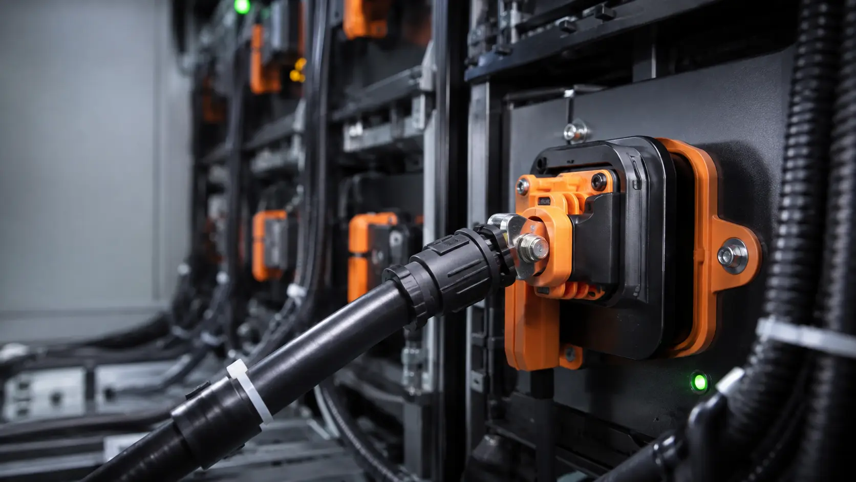
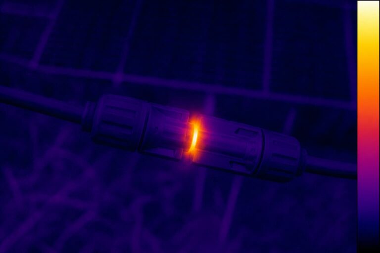
BESS connector temperature rise is the temperature gain above the surrounding cabinet air that happens when current flows through the contact system. It is set by three numbers: the current in amps, the contact and cable resistance in milliohms, and how well the heat can leave the connection. Voltage does not create the heat. A 1500 V DC connector can run cool at low current, and a 250 A connector can run hot if the cable is undersized or the contact resistance creeps up. This article explains where the heat comes from, how connector ratings are tested, and what to check before you commit a connector to a BESS cabinet.
Key takeaways
- Temperature rise follows I²R: current matters more than any other factor. Doubling the current quadruples the heat at the contact.
- Contact resistance and cable size are part of the same thermal system. A low-resistance contact cannot fix an undersized cable.
- Ratings are measured under defined lab conditions. Real cabinets add ambient heat, bundled cables, and restricted airflow.
- Ask for the derating curve and the temperature-rise test report, not just the amp rating on the datasheet.
- RFQ the connector and cable as one validated assembly, with the exact current profile and ambient temperature of your project.
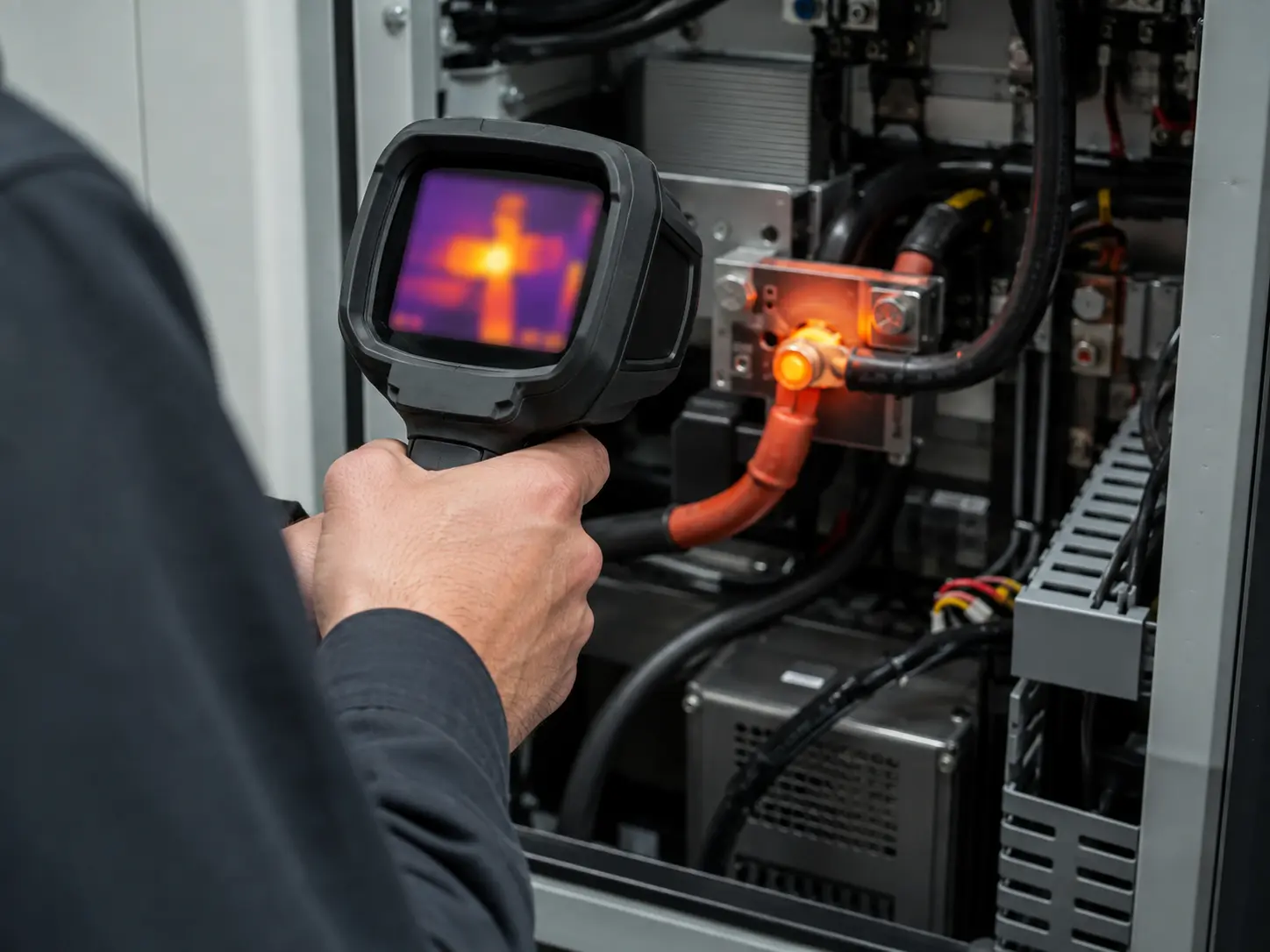
Every current-carrying connection dissipates heat. The physics is the same for a contact, a crimp, or a cable: the power loss equals current squared times resistance (Joule heating). In a connector, that resistance has three parts — the resistance of the mating interface, the resistance of the crimp or termination, and the resistance of the conductor itself. All three sit inside the same thermal path, and the heat from all three flows into the housing, the seal, and the cable.
The practical effect is a small table that should be part of every BESS connector review. The values below use typical contact resistances for high-current energy storage connectors; the math is the part to keep, not the example numbers.
| Current (A) | Resistance (mΩ) | Heat at that joint (W) |
|---|---|---|
| 150 | 0.5 | 11.3 |
| 250 | 0.5 | 31.3 |
| 350 | 0.5 | 61.3 |
| 350 | 0.2 | 24.5 |
At 350 A, the difference between 0.2 mΩ and 0.5 mΩ is about 37 W of heat at one connection point. A battery rack has dozens of connection points. In an enclosed cabinet with limited airflow, that heat accumulates and raises the local temperature around every component, including the cells.
The second point the table makes is about current. Raise the current from 250 A to 350 A, a 40 percent increase, and the heat at a 0.5 mΩ joint nearly doubles. This is why connector current rating decisions should be made against the real continuous load profile, not against the peak number on a datasheet.
A connector’s rated current is not a universal permission. It is the result of a defined test. Connector standards measure connector temperature rise by loading the mated contact with current until the temperature stabilizes, then recording the rise above ambient. Two reference points appear again and again in battery and connector work:
Both numbers are reference context for connector temperature rise, not a substitute for the standard that applies to your market. Standards get revised, and the applicable edition depends on the country, the voltage class, and the product category. What matters for this article is the concept: a current rating is tied to a connector temperature rise limit under specific test conditions. Change the ambient, the number of loaded contacts, the wire size, or the airflow, and the safe current changes with it.
Engineers often select a connector, then pick a cable that “fits the terminal.” In thermal terms, that is backwards. The cable is the largest resistor in the circuit, and it is also the main heat path out of the connector. An undersized cable heats up on its own, and that heat conducts back into the terminal, the crimp, and the housing. The result is a connection that passes the connector’s own rating test but runs too hot in the real assembly.
Cable ampacity depends on conductor cross-section, material, insulation temperature rating, ambient temperature, bundling, and installation method. In a battery rack, cables are often routed together in a confined space, which reduces the current each cable can carry. Industry practice and installation codes apply correction factors for ambient temperature and grouping. The same logic applies to the connector terminal: the terminal’s conductor range must accept the actual cable construction — conductor class, strand count, and insulation outer diameter — and the crimp must be made with the correct die for that terminal and conductor.
A practical rule for BESS work is to treat the connector, the terminal, the cable, and the crimp as one system. If the cable is too small for the continuous current, no connector change fixes it. If the crimp is poor, the added resistance appears at the joint and raises the temperature locally even when the cable and connector are both correctly rated.
Before you send a connector model to the BOM, check the expected connector temperature rise by running the load profile through these five steps:
Step 5 is where suppliers differ. A manufacturer that publishes a derating curve and a temperature-rise report at several currents has done the engineering. One that only prints a single amp number has left the thermal work to you.
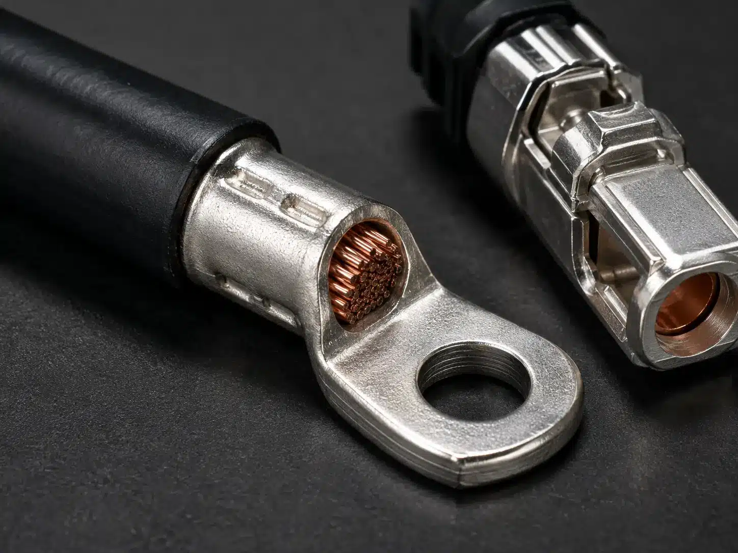
Connector current ratings come from single-contact tests in free air with new parts. Field conditions are rarely that generous. Contacts oxidize over time, mating cycles wear the plating, dirt raises resistance, and enclosures trap heat. A common engineering response is to size the connector so the continuous operating current stays at roughly 70–80 percent of the maximum rated current — in other words, 20–30 percent derating headroom.
Derating is not a substitute for asking the right question. The question is not “what is the rated current of this connector?” It is “what is the connector temperature rise at this current, with this cable, in this ambient, for the life of this project?” The answer comes from the manufacturer’s test data, and the test data should match your operating case.
This is also where the broader selection method matters. The 1500 V BESS connector selection guide on this site walks through the full set of dimensions — electrical, thermal, cable, mechanical, environmental, compliance, and production quality — and ends with an RFQ checklist you can send to a supplier as-is. Temperature rise is one dimension of that method, not a standalone check.
When the design includes a manual service disconnect for isolation during maintenance, the same thermal logic applies to that component. An MSD carries the same continuous current as the connector it isolates, and its contact and termination need the same derating review.
Use this list when you request a quote for BESS connectors and cable assemblies. Every item is something the supplier should be able to answer from documentation, not from memory:
| # | Ask | Why it matters |
|---|---|---|
| 1 | What is the rated current, and at what ambient and temperature-rise limit was it measured? | Turns a single amp number into a test condition you can compare against your cabinet. |
| 2 | What cable sizes and conductor classes are approved for this terminal? | Cable and terminal must match electrically and mechanically. |
| 3 | What is the contact resistance for the exact model and cable size? | The number you need for the I²R calculation. |
| 4 | Do you have a temperature-rise test report at continuous current? | Confirms the rating is backed by measurement, not by extrapolation. |
| 5 | Is there a derating curve for elevated ambient temperature? | Shows how the usable current falls when the cabinet runs hot. |
| 6 | What is the specified crimp tool, die, and inspection method? | Poor crimps add resistance where you cannot see it. |
| 7 | Which certification applies to this model for my target market, and does the certificate number cover this exact model? | A certificate for the family is not a certificate for the model. |
| 8 | What temperature range and flame rating apply to the housing and seal? | Materials age faster at temperature; the housing and seal are part of the thermal system. |
| Mistake | What actually happens | Better approach |
|---|---|---|
| Selecting by rated voltage first | A 1500 V rating does not reduce heat. Voltage drives insulation design, not temperature rise. | Start from continuous current and ambient temperature. |
| Using the peak current on the datasheet | The connector runs at or above its thermal limit during normal cycling. | Size against the continuous profile, then verify peaks. |
| Choosing a connector and cable separately | The cable heats the terminal, or the terminal cannot take the cable. | Validate the connector, terminal, cable, and crimp as one assembly. |
| Ignoring ambient temperature inside the cabinet | Lab rating at 25 °C does not apply inside a 45 °C enclosure. | Apply the derating curve at your worst-case ambient. |
| Accepting one amp number with no test report | No evidence the rating holds under your conditions. | Ask for the temperature-rise test report and derating data. |
Connector temperature rise is one number in the selection, but it is the number that most often separates a reliable BESS connection from a field problem. Send the continuous current, the worst-case ambient, the cable size, and the operating profile to the PVLinkTech engineering team, and the request a quote form will come back with a connector recommendation and the supporting ratings — not just a model number.

LET’S BUILD YOUR CONNECTION SOLUTION
Share your application, specifications, and estimated quantity. Our team will recommend a suitable connector solution and provide a quotation.
Low MOQ · OEM & ODM · Product Selection Support · Fast Quote Response