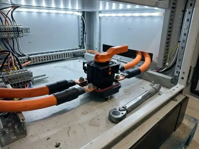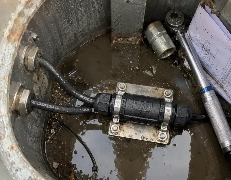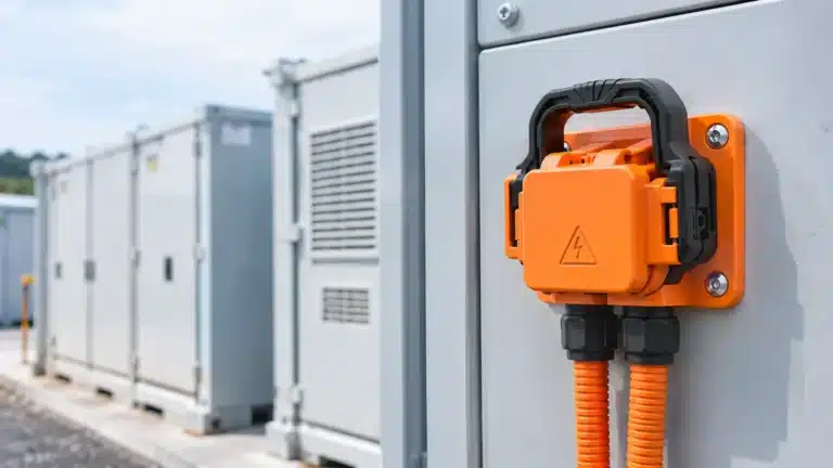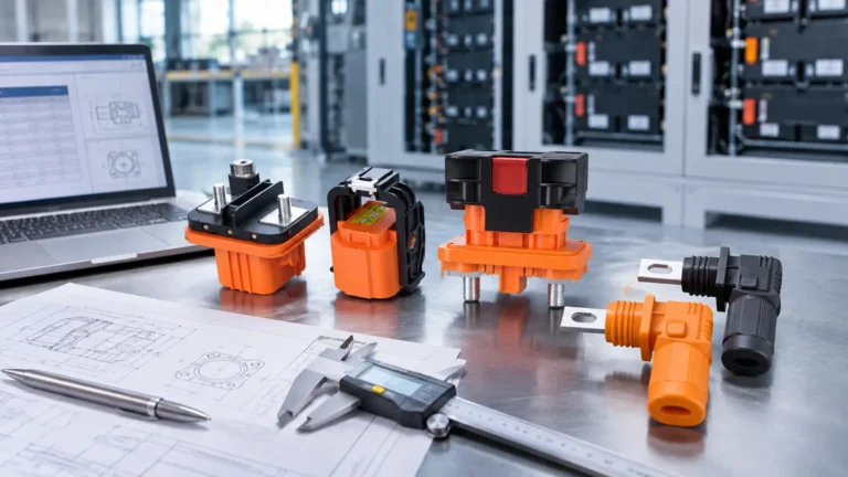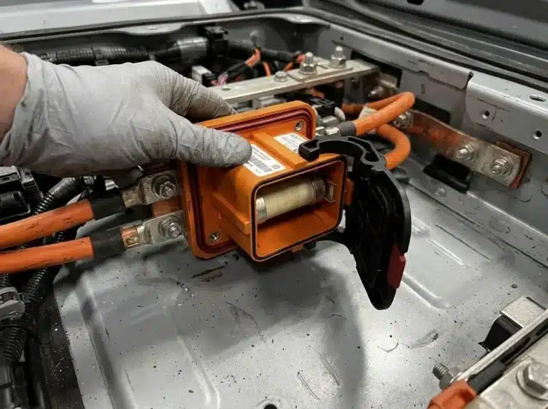



A battery service disconnect is the point where a technician physically opens a high-voltage battery circuit before working inside a cabinet, a rack or a pack, and the requirement for one comes from where the battery sits and how it will be serviced, not from the size of the plant. In the United States the rule sits in Article 706 of NFPA 70. Above 240 V DC nominal the same article also decides how many separate isolation points a series string needs. Four conditions drive the answer, and each one changes the part you buy.
| Item | Figure |
|---|---|
| Voltage above which a series string must be split for service | 240 V DC nominal |
| Distance limit for a disconnect within sight of the ESS | 3 m (10 ft) |
| Segments a 1,500 V DC string needs at that limit | 7 or more |
| Isolation layers in most containerized designs | unit, rack, pack |
| MSD-350 rating | 350 A at 1,500 V DC, IP67 |
A battery cannot be switched off. Open the contactor, open the inverter, and the cells still hold voltage, so a software shutdown leaves the DC bus live and the cabinet just as dangerous as before. What the code asks for is one identifiable place where the circuit is physically open and where a padlock can be fitted before anyone reaches inside the enclosure.
That narrow job sets two properties for a battery service disconnect. The device has to hold itself open with no control power available, because the control supply is off for the whole maintenance window. It also has to carry the full circuit current for years, because it stays in the current path of every cabinet it is fitted to between one service visit and the next.
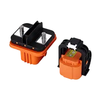
Our MSD-350 is built around both: 350 A rated current, 1,500 V DC, 4,000 V AC dielectric strength, IP67 once the gasket is seated on a flat panel, and a two-stage interlocking handle that separates the contacts before the handle comes free. Nothing in that description makes it a load-break switch, and no battery service disconnect should be asked to break load current.
Article 706 covers energy storage systems as installed, and 706.15 holds the rules that decide where a battery service disconnect goes. The 2023 edition sets four conditions. Most design reviews quote the first and forget the other three.
706.15(A) requires a means to disconnect the system from other sources of power, from utilization equipment and from premises wiring, so every ESS ends up with one device at the unit, and that device is usually the battery service disconnect.
Where a battery service disconnect may sit is fixed by 706.15(B). It has to be readily accessible, and it has to meet one of three options: inside the ESS, within sight and within 3 m (10 ft) of it, or capable of being locked open under 110.25 where it stands out of sight. Sight and distance apply together, so a disconnect 25 ft from the cabinet fails even when you can see it clearly.
A container split into a battery compartment and an electronics bay adds a second point. Once ESS circuits pass through a wall, floor or ceiling, 706.15(D) puts a readily accessible disconnect in the room that holds the battery.
Packs that can be pulled out and serviced in the field change the answer again. Where the battery is separate from the system electronics and subject to field servicing, 706.15(E) requires a disconnect for all ungrounded conductors, readily accessible and within sight of the battery.
| Condition | What NEC 706 asks for | What it means for the part |
|---|---|---|
| Every ESS | A disconnect from all sources and from premises wiring (706.15(A)) | One device per unit, marked (706.15(C)) |
| Location of the battery service disconnect | Inside the ESS, or within sight and 3 m (10 ft), or lockable open (706.15(B)) | Lock-off has to be designed in, not added later |
| Wall, floor or ceiling penetration | Readily accessible disconnect in the battery room (706.15(D)) | A second point appears at the room boundary |
| Battery separate from electronics, field serviced | Disconnect for all ungrounded conductors within sight of the battery (706.15(E)(1)) | The rack or pack carries its own isolator |
| Series string above 240 V DC | Provision to split into segments of 240 V DC or less (706.15(E)(2)) | More devices than one per string |
Site rules sit outside the equipment standard. UL 9540 treats the ESS as a unit and leaves installation to NFPA 70 and NFPA 855, which is where most of the awkward disconnect questions actually get answered.
The clause that catches people out is 706.15(E)(2). Where battery circuits exceed 240 V DC nominal between conductors or to ground, the design has to be able to disconnect the series-connected strings into segments of 240 V DC or less, so a qualified person can work on one section with the rest of the string still behind a barrier. Where that boundary falls is where a battery service disconnect sits.
The same clause permits non-load-break bolted or plug-in disconnects for exactly this purpose. That is the gap a battery service disconnect fills in a 1,500 V DC architecture: pulled by hand, not asked to interrupt current, lockable in the open position.
Divide the string voltage by that limit and the count of devices follows, before any product is chosen.

A 1,500 V DC string divided into seven segments of about 214 V, with an isolation point at each boundary, which is the arithmetic behind NEC 706.15(E)(2)
| Nominal string voltage | Segments at 240 V DC or less |
|---|---|
| 240 V DC | 1 |
| 400 V DC | 2 |
| 800 V DC | 4 |
| 1,000 V DC | 5 |
| 1,500 V DC | 7 |
Module voltage decides where the cuts fall, and some packs can be unbolted from the string instead of isolated at all, so seven is the floor for 1,500 V DC rather than a target to hit exactly. A single device on a 1,500 V string does not satisfy the segmentation rule whatever its current rating, and the gap tends to surface at plan review, not at the cabinet.
Neither location is wrong, and the deciding question is not preference: will the battery be serviced where it stands, or taken away from the electronics?
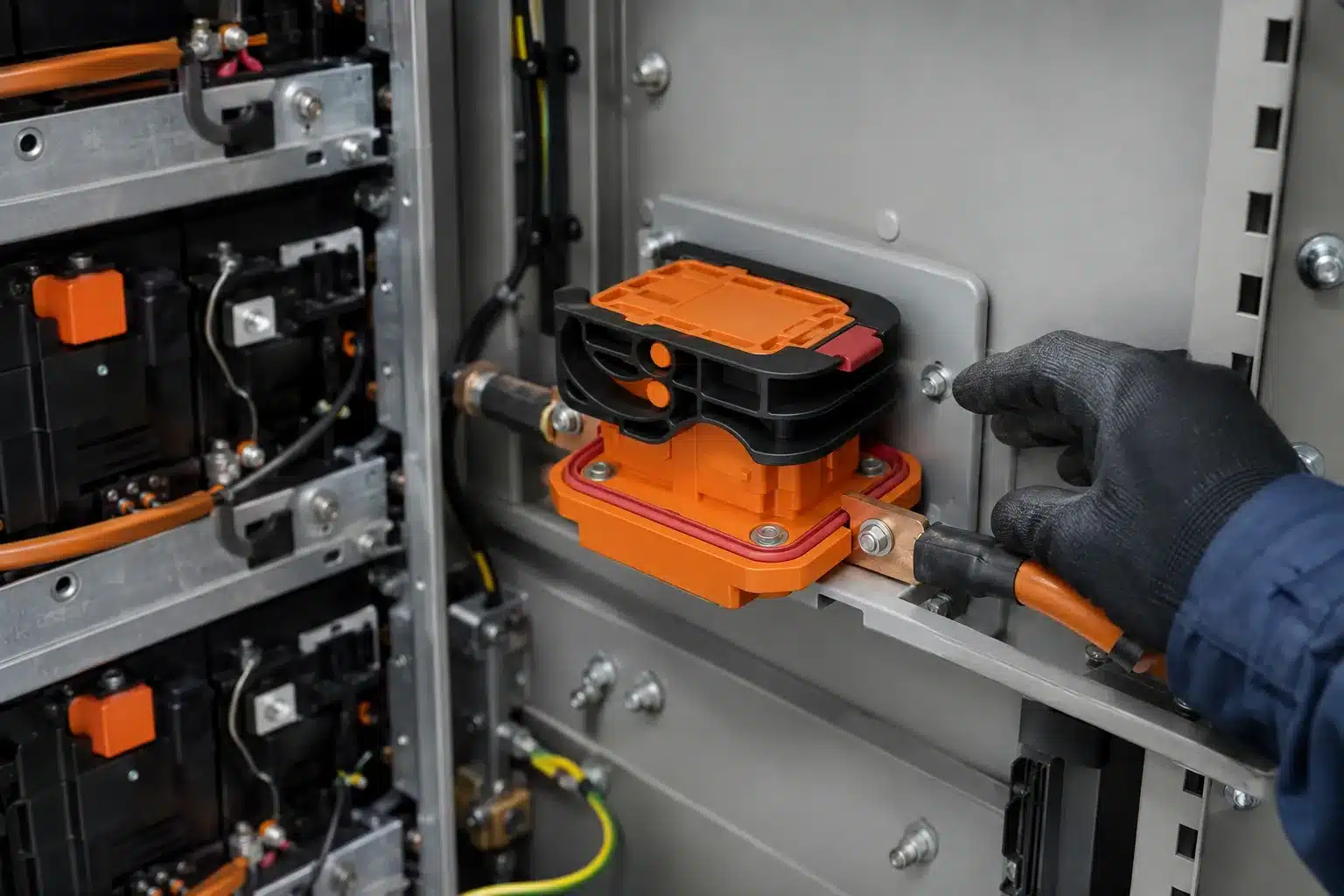
In a sealed unit, with battery, BMS and power conversion inside one listed assembly, an integrated battery service disconnect inside the cabinet satisfies 706.15(B) and no second device is needed on the pack. Once packs are field-serviceable and separated from the electronics, 706.15(E)(1) pulls the device toward the battery instead, mounted on the rack or on the pack itself and within sight of the cells it isolates.
Three practical tests settle where a battery service disconnect goes. Can the pack leave the cabinet for service? Are pack terminals still exposed after the rack device is open? Does an end-of-line or shipping test need isolation before the cabinet is complete?
| Layout | Where the point belongs | Reason |
|---|---|---|
| Sealed unit with integrated electronics | On a panel inside the cabinet | 706.15(B) option one is enough |
| Rack with field-serviceable packs | On the rack or the pack, within sight of the cells | 706.15(E)(1) |
| Packs removed and shipped separately | On the pack | The cabinet device travels with the cabinet |
| Battery room or split compartment | Room boundary plus pack | 706.15(D) and 706.15(E) both apply |
Service access is where a container design usually pays for itself. The 5 MW / 10 MWh container project case study covers routing space and serviceability inside a sealed cabinet, which is the same argument that decides whether the pack carries a point of its own.
Four devices share the same DC bus and each one has a separate job. Only one of them is the battery service disconnect. Substituting one for another is a common error in cabinet specifications.
| Device | Operated by | Its job | What it must not be asked to do |
|---|---|---|---|
| Fuse | Fault current | Clear a short circuit once | Reset, or be worked by hand |
| Circuit breaker | Manual or automatic trip | Interrupt overload and fault current | Serve as the only lock-off point |
| Contactor | A control signal | Switch load current every day | Hold open without control power |
| Battery service disconnect | A technician, by hand | Hold the circuit open and lockable | Interrupt load current |
Part of that confusion comes from the standards. UL 1977 and UL 4128 investigate connectors for isolation, and their scope excludes making or breaking a mated connection under load.
A part listed for isolation is not thereby listed for load break.
De-energize, open the disconnect, lock it, then verify the absence of hazardous voltage at the point of work. No work follows until that reading is on the meter, because the hardware confirms nothing by itself: a closed handle proves only that the contacts are closed, and an open handle proves only that they are apart.
Start with voltage, because the part is bought at a rating: use the highest figure the string can reach with the charger at its top setting, not the nominal value on the module datasheet.
Current, cable and fault duty belong in the same conversation. A 350 A device in front of 35 mm² cable is a system error, not a part error, because the cable, the lug and the terminal all have to carry the same current. The energy storage connector range on that bus is quoted in the same current bands, so the disconnect, the connector and the cable usually get sized in one pass.
Where the available fault current is high, the fuse upstream carries that duty and the disconnect only isolates. Most battery service disconnect specifications land on that arrangement, and it is the reason the device may be non-fused.
In a wet or condensing enclosure, sealing decides more of the specification than the current does. IP67 is a code, and the depth and duration behind it are declared by the manufacturer, so ask for the condition as well as the code. Panel flatness matters as much as the gasket does.
Cycles, force and marking space are usually settled last. For a part opened a few times a year, three hundred mating cycles covers the life of the cabinet. The field marking that 706.15(E)(4) requires, with nominal voltage and available fault current, needs real estate on the device or on a plate beside it.
| Figure | What to send | Example on the MSD-350 |
|---|---|---|
| Rated voltage | Maximum string voltage | 1,500 V DC |
| Continuous current | Current per point, and the cable | 350 A, 95 to 150 mm² suggested |
| Fault current | Available fault current, fused or not | Non-fused, isolate after the fuse |
| Environment | Sealing condition and ambient range | IP67 declared, −40 °C to +125 °C |
| Service life | Cycles, operating force, marking space | 300 cycles, 75 N or less, two-stage interlock |
Send the string voltage, the segment plan and the available fault current, and the reply comes back with a part number, a drawing and the document list for your market. Request a quote takes the six figures in one form, and the cable sizing follows on the 1500 V BESS connector selection guide once the string layout is fixed.
Send those six together and the battery service disconnect specification comes back in one reply, with the part number, the drawing and the document list. Where a program needs CE, RoHS or UL documentation, name the standard and the target market, because the paperwork is issued per model and per market rather than per series.
Yes. Manual service disconnect is the name the part carries in most BESS and EV documentation, and MSD is the abbreviation. The function is the same one: a physical isolation point that is opened by hand, locked open, and followed by a voltage check before work starts. Neither name implies that a battery service disconnect can interrupt load current.
Article 706 requires a disconnecting means for the energy storage system at any voltage, so a 48 V system needs a battery service disconnect too. The 240 V DC figure in 706.15(E)(2) governs something different: how far a series string above that level must be split for maintenance. Designers often read it as the threshold for needing a battery service disconnect at all, and then leave a low-voltage system without one.
Where the code allows bolted or plug-in devices that are not rated to break load, yes, provided three things hold: the device is only asked to isolate, it can be locked open, and its rating covers the string voltage. A plug-in battery service disconnect with a two-stage interlock does that job without tools. The rating matters, because a part designed for 1,000 V should not be sold into a 1,500 V string.
Not in every position. Inside the ESS, or within sight and 3 m of it, a battery service disconnect needs only ready access, and outside sight it has to be capable of being locked open. Most maintenance procedures add a lock requirement anyway, so a handle that takes a padlock or a hasp is the easier specification to defend at review.
Mount a battery service disconnect on the rack or pack when the battery is field-serviceable and separate from the electronics, since 706.15(E)(1) wants it within sight of the battery. Inside the cabinet when the unit is sealed with integrated electronics. Either way the sealing face has to be flat. A warped or painted-over panel leaves the gasket unseated, and the IP67 rating the part was tested to no longer describes the installed assembly.

LET’S BUILD YOUR CONNECTION SOLUTION
Share your application, specifications, and estimated quantity. Our team will recommend a suitable connector solution and provide a quotation.
Low MOQ · OEM & ODM · Product Selection Support · Fast Quote Response