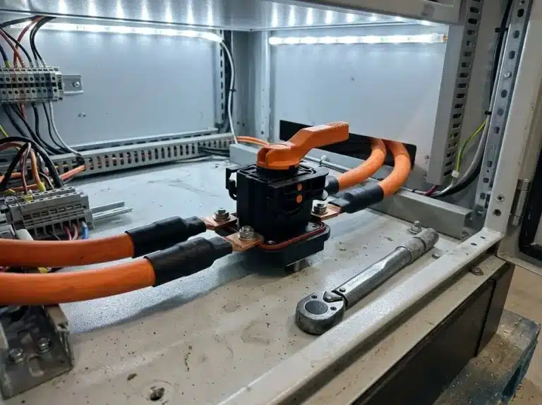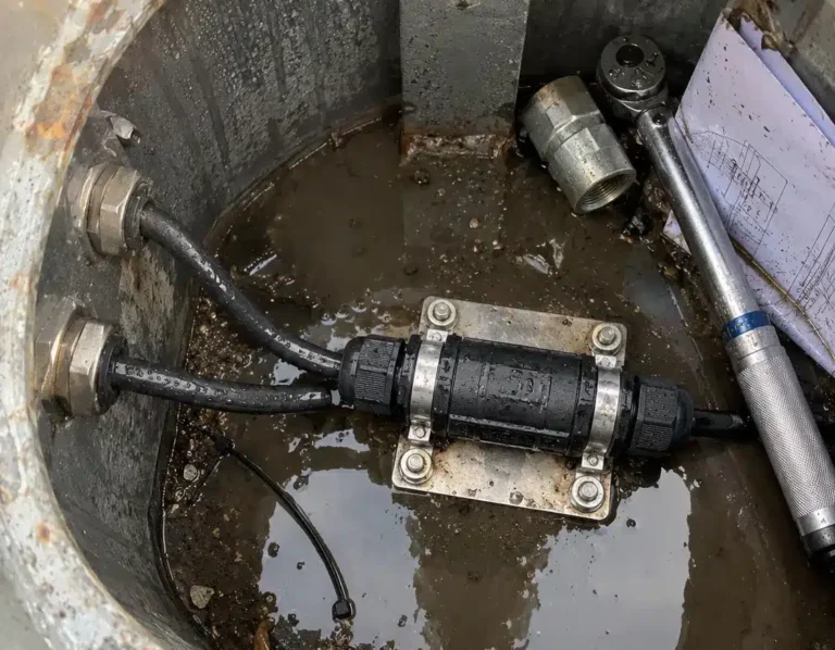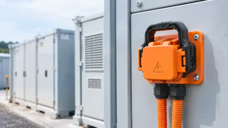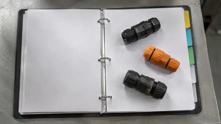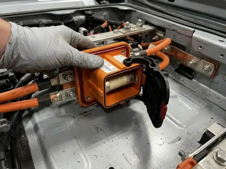


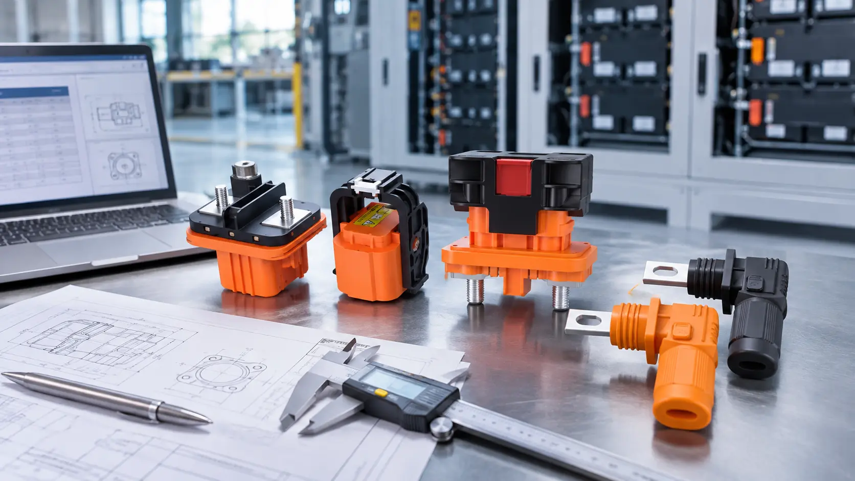
A complete energy storage connector RFQ helps a supplier understand the electrical requirements, connection dimensions and protection arrangement before recommending a product.
For a busbar connector or manual service disconnect (MSD) quotation,start with the system DC voltage, continuous current, expected cabinet temperature, available fault current and protection arrangement.Then provide the busbar dimensions, panel cutout, mounting-hole pattern and cable details where applicable.
This guide explains which information to send, which details the supplier should confirm, and what to do if you only have an existing connector or incomplete drawings.
Send the system voltage, continuous current, expected operating temperature, available fault current and protection arrangement. Include busbar width and thickness, panel cutout and mounting-hole dimensions, cable and lug details where applicable, quantity and target delivery date.
If some information is not available, mark it as “to be confirmed” and send the drawings or photos you have. Ask the supplier to confirm the product ratings, dimensions, derating and installation requirements.
Three documents decide the price, and they live with three different companies. The short-circuit study sits with the electrical engineer. The busbar cross-section is on a structural drawing held by the rack integrator. The panel cutout belongs to whoever builds the cabinet. A buyer holding only the load list can still open one, but every figure that comes back will carry a condition.
In practice the message reads 350 A, 1500 V, storage cabinet, and the answer confirms that a 350 A part exists in the 1500 V class. Nobody has quoted anything yet.
The figure that goes missing is rarely the current, and it is usually the busbar thickness or the hole spacing, because neither can be read off a photo of the connector. Both live on a drawing, and that drawing sits in another building, which is where most energy storage connector RFQ threads stall.
The following checklist separates the information normally supplied by the buyer or system designer from the details the connector supplier should confirm. Provide the information you have and mark missing items as “to be confirmed.”
| Information | What to provide or confirm | Who normally provides it |
|---|---|---|
| System DC voltage | Operating voltage and relevant voltage requirements | Buyer or system designer |
| Continuous current | Expected continuous current for each circuit | Buyer or system designer |
| Operating temperature | Expected ambient temperature around the connector | Buyer or system designer |
| Fault and protection information | Available fault current, protection device and its location, if known | System designer |
| Busbar dimensions | Busbar width and thickness at the connection point | Buyer or mechanical designer |
| Panel interface | Panel cutout, mounting-hole pattern and available space | Buyer or cabinet designer |
| Cable and termination | Cable conductor size, lug and termination type, where applicable | Buyer or system designer |
| Quantity and delivery | Required quantity, project schedule and delivery destination | Buyer |
| Product confirmation | Product ratings, dimensions, derating, torque and applicable documentation | Supplier |
For standard catalogue parts, the supplier normally provides the product drawing and installation instructions. Tell the supplier about any special environmental, certification, marking or packaging
requirements that apply to your project.
Get the top six into one message and the first reply can carry a dimensioned drawing instead of a question. Packaging and acceptance values are not on this list, because they belong to a single-part inquiry. If that is what you price, the general eight-item RFQ list covers it.
The electrical information normally needed for an initial connector review includes the system DC voltage, continuous current and expected ambient temperature. Available fault current and the protection arrangement are also important when reviewing the complete system and its components.
If the fault study or protection design is not finished, identify the missing information in the RFQ and ask what is needed before final product approval.
Voltage class deletes product families before anyone prices an energy storage connector RFQ. On our side a 120 A bolt connector stops at 600 V DC, the 250 A bolt model reaches 1000 V DC, and the 400 A model plus the whole copper bar range run to 1500 V DC. Send 1500 V and the 120 A family leaves the conversation.
Continuous current means the current the circuit carries for hours, measured or estimated at the temperature inside the cabinet. A nameplate rating is usually stated at 25 degrees C, and a container in the sun at midday is not at 25 degrees C. Send both, then ask what derating applies. That ambient figure is the one an energy storage connector RFQ most often leaves out. The CN range of energy storage connectors is published with a rated current per model, and the same question applies to every model in it.
| Number | What it fixes on the busbar side | What it fixes on the MSD side |
|---|---|---|
| System voltage class | Which carrying classes exist for your circuit | Whether a 1500 V DC disconnect is applicable at all |
| Continuous current at ambient | The class you order, from 120 A to 600 A | Whether the 350 A frame is inside its rating |
| Available fault current | Terminal stress and coordination with the protection device | Check the applicable ratings and coordination requirements of the disconnect and protection arrangement with the supplier and the responsible system designer. |
Available fault current may be needed when reviewing equipment ratings,protection coordination and applicable field-labeling requirements.The exact requirements depend on the system, installation location and applicable standards. Provide the available fault-current information
when known, and ask the system designer to confirm the relevant requirements.
Under the field labeling requirements of NEC Article 706 in NFPA 70, it is printed on the label at the battery system. Somebody on your project already calculated it, so ask for that number instead of letting a supplier size around a blank.
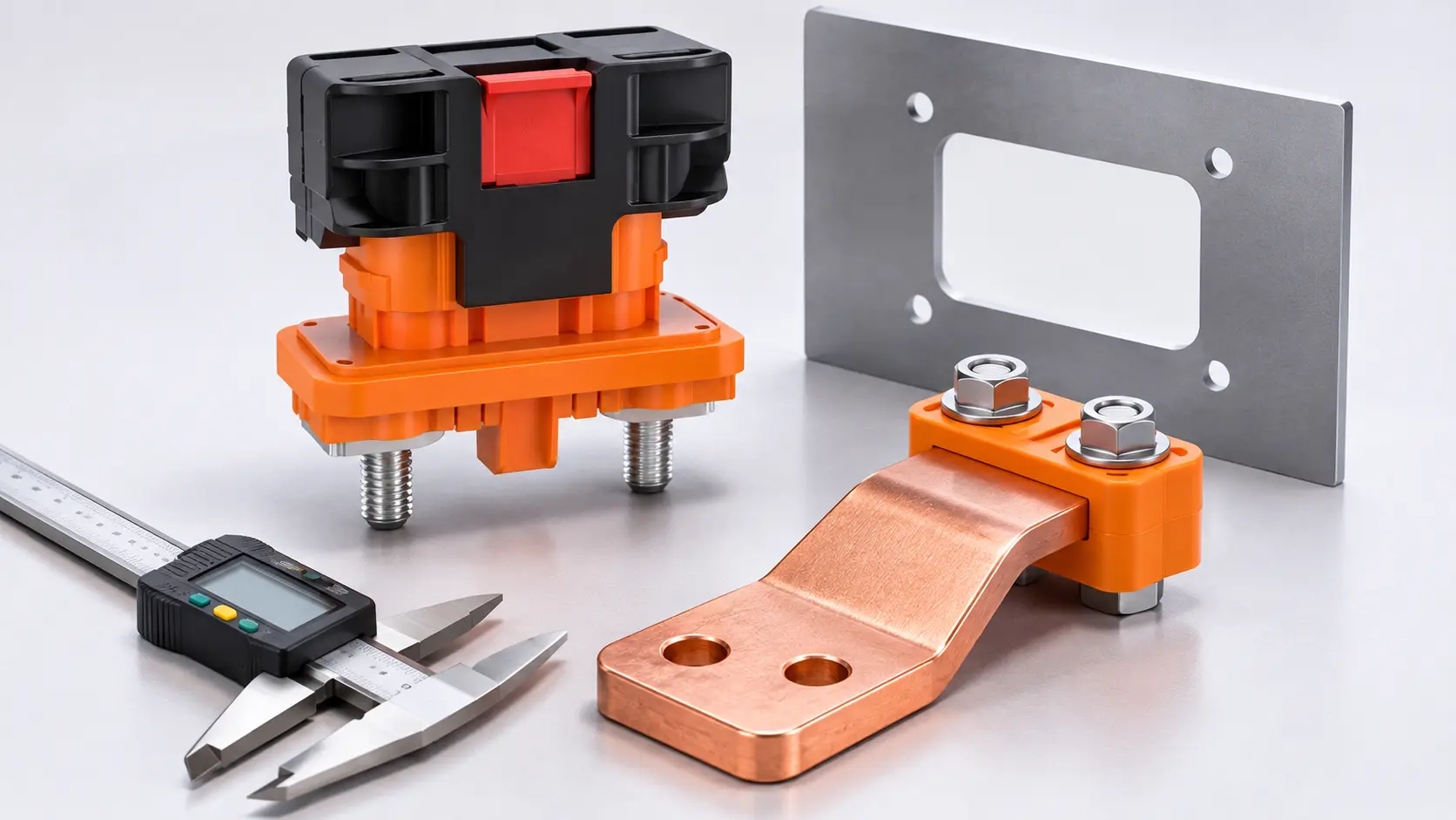
For a busbar connector quotation, provide the busbar width and thickness at the connection point. Also send the panel cutout and mounting-hole pattern if the connector is panel-mounted.
A dimensioned drawing is preferred. If no drawing is available, provide clear photographs and the measurements you can verify, and ask the supplier to confirm the fit using the current product drawing.Everything about a battery busbar connector follows from the carrying class you picked, so the busbar half of an energy storage connector RFQ comes down to two geometry figures.
| Figure | What it has to match | Where buyers go wrong |
|---|---|---|
| Busbar width by thickness | The clamp opening: 15 x 3 mm on the 120 A bolt model, 20 x 4 mm on the 250 A models, 25 x 6 mm on the 350 A and 400 A models, 30 x 8 mm on the 600 A copper bar model | Sending the width and leaving out the thickness |
| Panel cutout and mounting holes | 20.0 mm cutout with four M4 holes on the 120 A, 23.0 mm with four M4 on the 250 A, 27 mm with four M4 on the 400 A | Quoting from a catalogue outline instead of the cabinet drawing |
A busbar is a machined or laminated conductor, and its dimensions come from whoever designed the stack. We cannot derive 30 x 8 mm from 600 A. A taller bar and a wider bar reach the same current with different thermal behavior, so the section has to come from you.
The cutout is the dimension that shows up late, after the part is cut and the drawing is signed. A connector ordered against the wrong cutout arrives as a correct part that will not bolt to the cabinet, and the fix is a new panel.
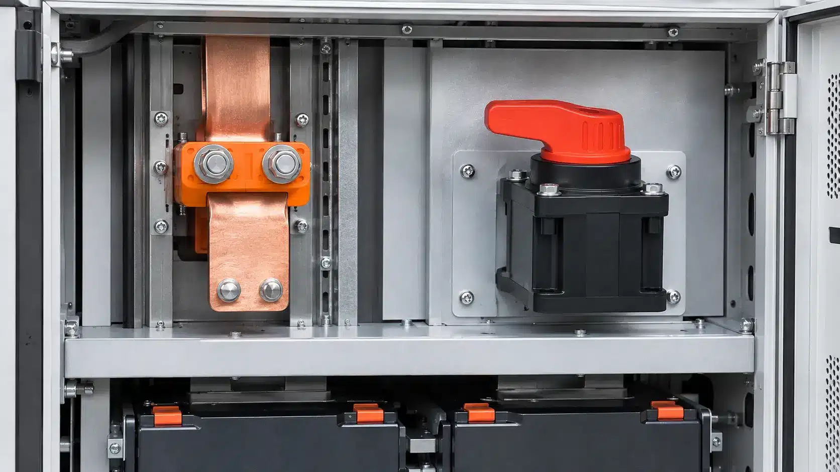
A busbar connector and a manual service disconnect may be used in the same energy storage system, but each component must be reviewed against its own ratings and installation conditions.
Check the system voltage, continuous current, temperature derating,connection dimensions and applicable protection requirements. The system designer and supplier should confirm the complete configuration using current product documentation.
A 350 A copper bar connector and a 350 A disconnect look matched on paper, and they are matched, right up to the point where the cabinet runs warm. Both lose capacity as the ambient climbs and were specified at the same nominal figure, and the pair that looked right at 25 degrees C has nothing left at 45.
| Continuous current | Busbar side that fits | Disconnect side | What has to change | Why |
|---|---|---|---|---|
| Up to 120 A | 120 A bolt, 600 V DC ceiling | MSD-350 sits far above the load | Nothing, if the system is 600 V DC or lower | Voltage class rules here, not current |
| 250 A | 250 A bolt at 1000 V DC, or 250 A copper bar at 1500 V DC | MSD-350 carries it with 100 A in reserve | Pick the bar by voltage class | Both exist, and only one fits your bus |
| 350 A | 350 A copper bar, 25 x 6 mm, 1500 V DC | MSD-350 sits exactly at its rating | Check cabinet temperature before both are approved | No margin on either part |
| 400 A | 400 A bolt, or 600 A copper bar | MSD-350 is below the circuit current | Review a suitably rated alternative or an engineered circuit design. | A disconnect cannot be rated up |
| 600 A | 600 A copper bar, 30 x 8 mm, cable to 185 mm² | Outside a single MSD-350 | Review the system configuration and available disconnect options with the responsible engineer and supplier. | Isolation is per circuit, not per cabinet |
For circuits above the rating of a particular MSD model, ask the supplier about available alternatives and provide the system designer with the relevant product documentation. Any change to the circuit or isolation arrangement should be assessed as part of the complete system design.
The MSD-350 page sets out what that frame covers, so ask for two disconnects and the answer comes back as a drawing. Ask for one at 600 A and the answer is a refusal, which costs you a week.
The six figures in that energy storage connector RFQ have an order, and it is not the order they appear on your drawings.
Each step depends on the one before it, which is why the order matters more than the form
Review these items together before approving a part. An appropriate current rating does not by itself confirm that the voltage rating,mechanical interface or protection arrangement is suitable.
Skip step three and the coordination lands on the supplier, who cannot do it without your study. Leave step six to the end and the drawing revision arrives after the parts are cut.
Three of the nine are decided by the model drawing itself
If a supplier asks for something already on the part drawing, they are quoting a different part or building to your drawing. Either answer is worth having before a deposit goes out.
| Detail | What to do |
|---|---|
| Tightening torque | Ask the supplier for the torque specified in the current product drawing or installation instructions. |
| Plating and materials | State special corrosion or environmental requirements and ask the supplier to confirm the available finish. |
| Marking and certification | Identify the destination market and any project-specific marking or certification requirements. |
| Packaging | State any special labeling, packaging or delivery requirements. |
Copy the template below and complete one entry for each circuit.If a value is not yet available, enter “to be confirmed.”Attach the relevant drawing or clear photographs where possible.
A row per circuit answers most of what a supplier would otherwise ask by email. Fill one table per cabinet, and the energy storage connector RFQ reads in a single pass instead of a paragraph per part.
Complete the available details below. Mark unknown specifications as “To be confirmed”. Copy the completed RFQ and send it with your drawings or photos.
| Circuit ID | Continuous current | System voltage | Conductor at the joint | Disconnect on this circuit | Protection device |
|---|---|---|---|---|---|
| B1 rack to DC bus | 250 A | 1500 V DC | 20 x 4 mm bar | Yes, one per rack | Fuse, 400 A |
| B2 rack to bus | 250 A | 1500 V DC | 50 mm² cable plus lug | Yes, one per rack | Fuse, 400 A |
| PCS feeder | 600 A | 1500 V DC | 30 x 8 mm bar | No, cabinet level | Breaker, 800 A |
| Aux DC | 40 A | 48 V DC | 10 mm² cable | No | Breaker, 63 A |
Three rows need a busbar connector, two need a disconnect, and the fourth needs neither. Writing that last row down anyway keeps the supplier from pricing it into the total.
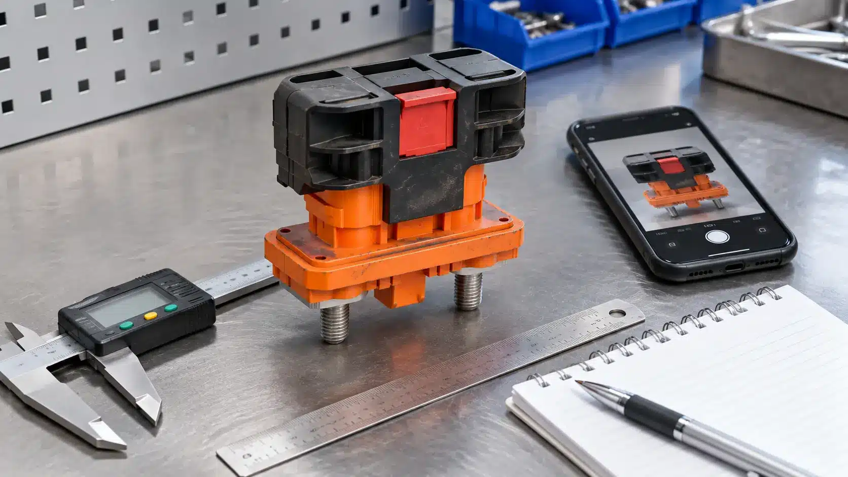
If you do not have a drawing or part number, send the supplier:
Voltage comes off the system label or the inverter nameplate, and tCheck the available system documentation and equipment labels for relevant ratings. Ask the responsible electrical engineer for the available fault current and protection information when it is not
documented on the equipment.
Busbar thickness comes from calipers on the bar, measured at the clamp point and not at the end where it may be machined.
Cable size is printed on the jacket, which stretches with age, and when the print is gone you measure the conductor strands and count them. A 95 mm² cable and a 120 mm² cable look alike and take different lugs, which is why a photograph rarely settles a retrofit.
Send us the information you have, such as system voltage, current, busbar dimensions, drawings or photos. Our team will review your requirements and identify any additional information needed for product selection and quotation.
Technical guidance for energy storage busbar connectors, manual service disconnects, electrical protection and BESS integration.
One message with two sections gets a coordinated answer, so send the connection table first, then list the circuits that need a busbar connector and the circuits that need a disconnect. Two separate messages usually produce two quotes built on different assumptions about the same cabinet, and reconciling them takes longer than writing one energy storage connector RFQ.
Send the design stage and the expected range. A study in progress still carries a calculated figure at the design stage, and that figure keeps the disconnect selection from running ahead of the protection. Mark it preliminary so nobody treats it as final, because waiting for the finished study holds the mechanical design back for weeks.
They can share a cabinet and not the same circuit. The disconnect is rated to 350 A, so a 600 A path needs its isolation split across two circuits, each with its own disconnect. That layout is normal in containerized systems, and it usually costs less than hunting for a single oversized disconnect that nobody builds.
No. It isolates a circuit so a technician can work, and it is not built to interrupt fault current. A fused version can carry a fuse, and a non-fused version like ours has no fuse cavity at all. Clearing a fault belongs to the fuse or the breaker, and the coordination study belongs to whoever sized that device.
Not on the same cabinet. The busbar connector seals against the panel it mounts through, and the disconnect seals at its mating interface, so the two surfaces do different jobs. Match each part to its own location, then confirm the lower figure is acceptable for the compartment it sits in.
Calipers numbers and photographs of both surfaces, taken with a tape measure in frame. Add the system voltage from the label and the cable print from the jacket. For the fault current, photograph the field label. A retrofit inquiry with those five items goes to the same engineering review as a new build. It just needs one confirmation step.

LET’S BUILD YOUR CONNECTION SOLUTION
Share your application, specifications, and estimated quantity. Our team will recommend a suitable connector solution and provide a quotation.
Low MOQ · OEM & ODM · Product Selection Support · Fast Quote Response