

Need waterproof connectors?Request a Quote →
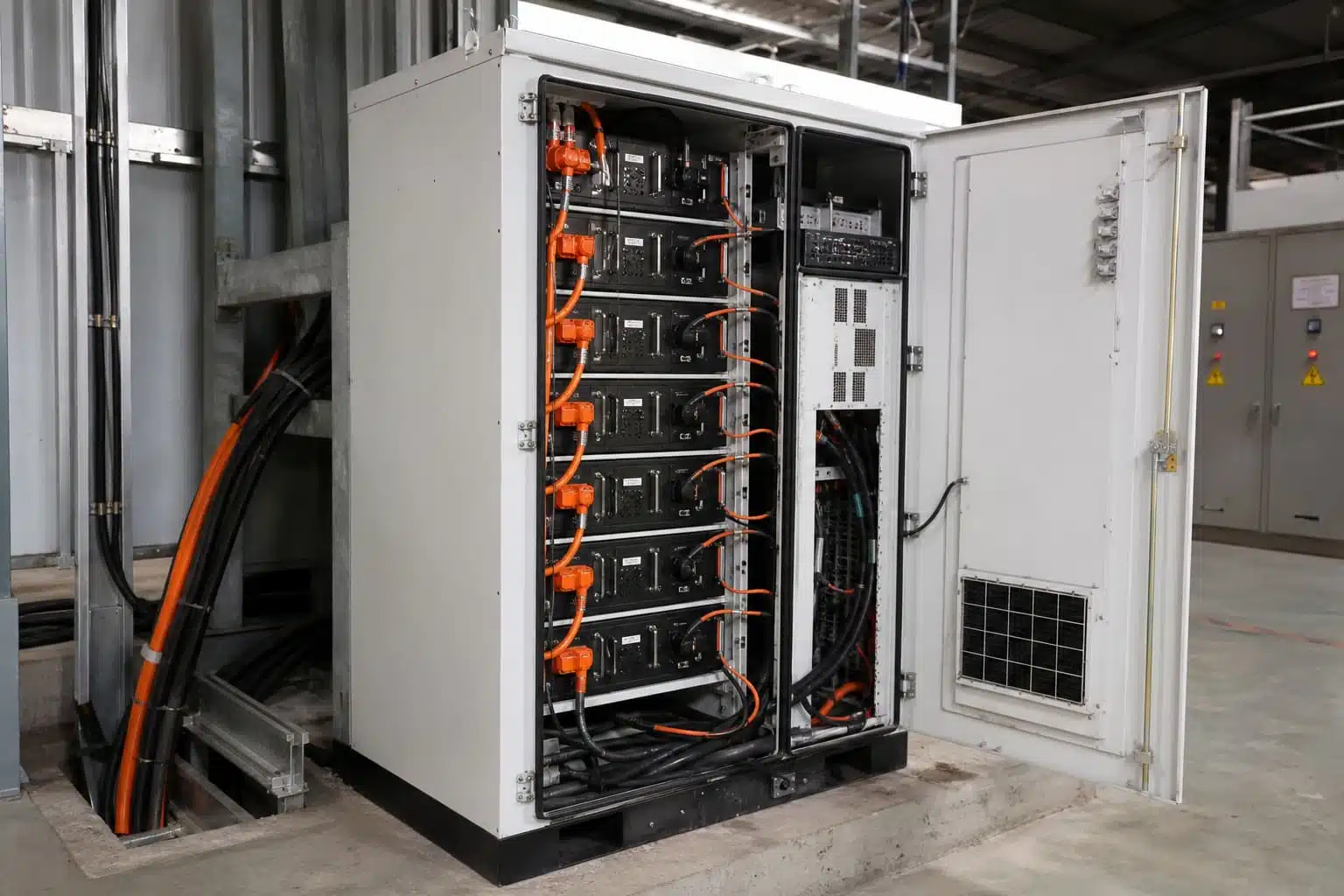
A specification-first guide for energy-storage engineers, battery-pack designers, system integrators, and procurement teams.
A typical RFQ lands with four words: “1500V BESS connector needed.” No cable size. No ambient temperature. No duty cycle. If the supplier quotes a part from that alone, the quote is incomplete. Not because the connector is bad, but because the specification that actually matters was never stated.
A 1500V rating is a starting point, not a decision. The connector sits inside a thermal, mechanical, environmental, and human-safety system. Choose it on headline voltage and ampere number alone, and you can end up with a part that overheats at 80% load, fails in a condensing cabinet, or lets an operator touch live parts during service.
This guide covers the eight dimensions that determine whether a BESS connector selection will hold up in your application: electrical, thermal, cable and termination, mechanical, environmental, safety, compliance, and production quality. The final section gives you an RFQ checklist you can send to a supplier as-is. The dimensions interact: a cable that is too small raises temperature rise, which changes the derating decision, which can change the connector size.
| Term | Meaning |
|---|---|
| BESS | Battery energy storage system: the complete battery-pack, rack, and power-conversion system. ( Overview ) |
| DC link | The DC bus that connects battery racks to the inverter or power conversion system (PCS). |
| Continuous current | The current a connection carries steadily in normal operation. |
| Peak current | A short-duration higher current, defined together with its duration and repetition. |
| Temperature rise | Connector temperature above a reference ambient under stated test conditions. |
| Derating | The reduction of rated current when operating conditions differ from test conditions. |
| Touch-safe | Construction that prevents accidental contact with live conductive parts. |
| Keying | Mechanical features that prevent incorrect mating, such as polarity reversal. |
| HVIL | High-voltage interlock loop: a low-voltage circuit that proves connector continuity before energizing. |
Before any rating discussion, fix the physical location and function. Battery module, rack, cabinet, PCS/DC bus, combiner, service interface, or auxiliary circuit. Each location has different electrical stress, access, and service expectations.
Ask these questions:
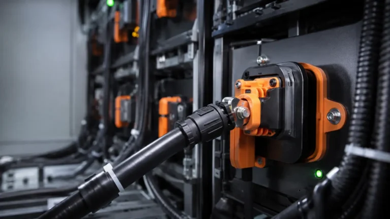
Location drives touch safety (a service interface is handled more often than a fixed busbar link), keying requirements, ingress protection, vibration exposure, and mating-cycle counts. Two connectors with identical ratings can be wrong or right purely because of where they sit in the system. That is why application position comes first in BESS connector selection. Learn where PVLinkTech’s energy storage connectors fit across module, rack, and cabinet layouts.

Nominal system voltage is not the design voltage. Define:
Creepage and clearance belong to the complete connector-and-installation design, not to the label. A 1500V DC rating on a datasheet does not by itself prove the part meets creepage and clearance in your enclosure, at your altitude, with your pollution degree. Verify the applicable standards and project requirements with the responsible engineer before freezing a part number. As a market example, manufacturers such as TE Connectivity publish 1500V high-current BESS connector options whose listed current values are tied to specific cable sizes and test conditions; always verify a current value against the exact datasheet before using it in your design. Getting the voltage envelope wrong invalidates every later step in BESS connector selection, so this gate comes first.
A single ampere value is not a thermal input. Record:
Catalogue current ratings depend on the test setup: conductor size, ambient temperature, and the allowable temperature rise used in testing. The same connector listed at 200A on a short test lead can run much hotter on a smaller cable inside a sealed cabinet. If you do not have logged data, instrument the prototype or the first pilot unit; a current profile estimated from nameplate values is usually optimistic. Give the supplier a profile, not a number.

Temperature rise is the connector temperature above a reference ambient under stated conditions. It is the central engineering decision in high-current DC connections, because it is where most field failures start.
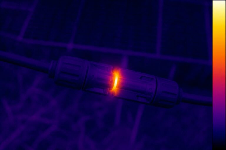
Heat comes from contact resistance, crimp quality, and the cable conductor itself, then it is modified by enclosure heat, adjacent components, airflow, and installation density. Two otherwise identical connectors can differ measurably in temperature rise depending on termination quality and cable size. Temperature rise is also where the most common BESS connector selection mistakes happen, because the datasheet number is rarely the number inside the cabinet. Infrared checks on a loaded prototype are a fast way to confirm the crimp and cable terminations before the design is frozen.
Ask for derating curves and their test conditions, not just a maximum current headline. Confirm the polymer, contact, cable, and touch-temperature limits for your application. Then validate in the representative condition: your cable, your enclosure, your orientation, your ambient, your load profile. That is the only test that predicts field performance.

The connector and the cable fail or succeed together.
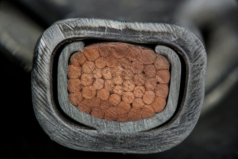
Specify conductor cross-section, material, strand class, plating, insulation and jacket material, outer diameter, bend radius, and approved temperature rating. Then confirm that the crimp barrel or termination is compatible, including the tooling and process window. A crimp that is too loose raises contact resistance, too tight damages strands, and the wrong die deforms the barrel.
Separate conductor size from the sealing range. A connector that seals around a cable OD of 10 mm does not automatically accept a 25 mm² conductor with a thick jacket. Consider cable mass, pull, vibration, busbar transitions, strain relief, and service handling. Termination compatibility is a common blind spot in BESS connector selection because it is not visible on the connector itself.
As a manufacturer-side example, PVLinkTech’s energy storage series covers cable cross-sections from 6 mm² to 95 mm² (10 AWG to 3/0 AWG) across its 50-350A range. Treat any cross-section-to-current mapping as product-specific: ampacity depends on conditions and standards, and no universal rule applies.

High-voltage DC does not forgive mistakes after the fact. Define:
A small FMEA-style table is a practical way to pin down what you need:
| User error | Consequence | Design control | Verification |
|---|---|---|---|
| Polarity reversal | Short circuit, cell damage | Keyed housings, color coding | Insertion test, keying gauge |
| Incomplete mating | High resistance, overheating | Positive lock, audible/visual click | Pull test, mating-cycle test |
| Wrong cable sealing | Water ingress, corrosion | OD-range marking on gland | Seal test at max/min OD |
| Live disconnect | Arc, injury | HVIL interlock, service sequence | Interlock test, procedure review |
DC circuits must be isolated and verified de-energized by qualified personnel before any connection or disconnection work.

Environmental requirements turn BESS connector selection from guesswork into a testable specification. Translate the installation environment into testable requirements:
IP67 or IP68 alone does not cover every outdoor or BESS environment. A sealed connector in a condensing cabinet can still suffer internal corrosion; a vibration-tested part can still fail a poorly supported cable. Write the environment down as numbers, not adjectives.
A certificate is not a substitute for a documented production process, and production control is where a BESS connector selection is proven repeatable. Procurement needs to distinguish a plausible part from a production-ready solution.
Check the applicable standards and certificates, and the exact part-number scope of each certificate. Ask for temperature-rise, dielectric withstand, insulation resistance, mechanical endurance, sealing, vibration, and material data as required. Then look at production controls: tooling, work instructions, in-process verification, traceability, change control, lot control, and outgoing inspection. Our quality control and certificates pages show how production controls are documented.
For custom cable assemblies, add first-article approval, a test plan, labeling, packaging, and service documentation. A certificate issued for one part number does not automatically cover a modified variant. Insist on validation data tied to the exact part you plan to buy; that is what separates documented BESS connector selection from brochure-based selection.
Use this checklist as the minimum input for any BESS connector selection conversation, and send it to your supplier together with your drawings:
| # | RFQ input |
|---|---|
| 1 | Application location and mating interface |
| 2 | Maximum working voltage and electrical architecture |
| 3 | Continuous and peak current profile, with durations and duty cycle |
| 4 | Cable conductor and outer-diameter data |
| 5 | Ambient, enclosure, temperature-rise target, and derating conditions |
| 6 | IP, environmental, and mechanical requirements |
| 7 | Touch-safe, keying, locking, HVIL/sensing, and mating-cycle needs |
| 8 | Standards, validation tests, traceability, annual volume, sample timing, and customization needs |
In BESS connector selection, the fastest route to a reliable 1500V part is a complete application profile, validated as a connector-cable-enclosure-process system. The minimum RFQ inputs are: location, maximum working voltage, current profile, cable data, thermal conditions, environment, safety features, and compliance needs.
Send PVLinkTech your BESS voltage, current profile, cable data, thermal conditions, environment, safety features, and annual volume for a connector or cable-assembly review. We build 1500V DC energy storage connectors from 50A to 350A with IP67 sealing and UL94 V-0 housings, and if a part is not right for your application, we will tell you.
Request a Quote

LET’S BUILD YOUR CONNECTION SOLUTION
Share your application, specifications, and estimated quantity. Our team will recommend a suitable connector solution and provide a quotation.
Low MOQ · OEM & ODM · Product Selection Support · Fast Quote Response