

Need waterproof connectors?Request a Quote →
A symptom-to-cause field guide for PV installers, O&M teams, and quality managers — what to check, what evidence to record, and how to prevent repeat failures.
PV strings can remain energized whenever they are illuminated, and system topology or stored energy can add risk that is not obvious from the outside. Before any inspection, disconnection, or repair: isolate the affected circuit, follow the site’s approved lockout/tagout procedure, verify the circuit is de-energized with an appropriate meter, and use qualified personnel with the required PPE.
Note: “MC4” is a registered trademark of Stäubli Electrical Connectors. The failure patterns and checks in this article apply to MC4 and MC4-style PV connectors from any manufacturer.
When a PV string loses output or a connector shows heat damage, the first reaction is usually “replace the connector.” That reflex skips the evidence needed to find the actual cause — and it is often why the same failure shows up again a few months later.
Most MC4 connector failure cases share a small set of root causes, but the visible damage rarely points to one of them directly. MC4 connector failure is rarely one clean event. Multiple causes can coexist: a marginal crimp can overheat a connector that was also partially mated; moisture can accelerate the corrosion that started at a damaged seal. The fastest route to a useful answer is to work from the observed symptom backward.
| Observed symptom | Plausible causes | Evidence to collect | Immediate disposition |
|---|---|---|---|
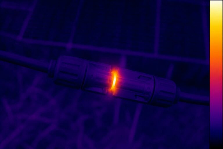
| Localized heating at one connector | Bad crimp, undersized conductor, loose contact | Thermal images, load current, crimp cross-section | Quarantine; do not reuse |
| Melted or discolored housing | High-resistance termination, partial mating, sustained overload | Photos, ambient temperature, string current history | Quarantine; preserve for analysis |
| Intermittent string current | Partially seated contact, loose cable entry, broken lock | Connection logs, weather and vibration context, contact position | Isolate and inspect before reconnecting |
| Corrosion or visible moisture | Water ingress path, wrong cable diameter, damaged seal | Ingress orientation, cable routing, seal condition | Quarantine; document the entry path |
| Loose cable entry | Wrong jacket diameter, failed strain relief | Jacket OD against seal spec, pull test result | Replace with a correctly sized assembly |
| Contact backing out | Incomplete insertion, wrong tooling, damaged retention | Insertion records, manufacturer gauge check | Replace the contact |
| Broken lock | Off-axis assembly, repeated connect/disconnect, material aging | Lock condition photos, mating history | Replace the pair |
| Repeated failure at same location | System stress: grouping, poor ventilation, vibration, ampacity | Layout drawings, thermal profile, load data | Correct the system-level cause |
Symptom-to-cause quick reference — recommended featured-snippet target
Treat every cause in the table as a hypothesis until the evidence supports it. Do not diagnose an MC4 connector failure from a photo alone.
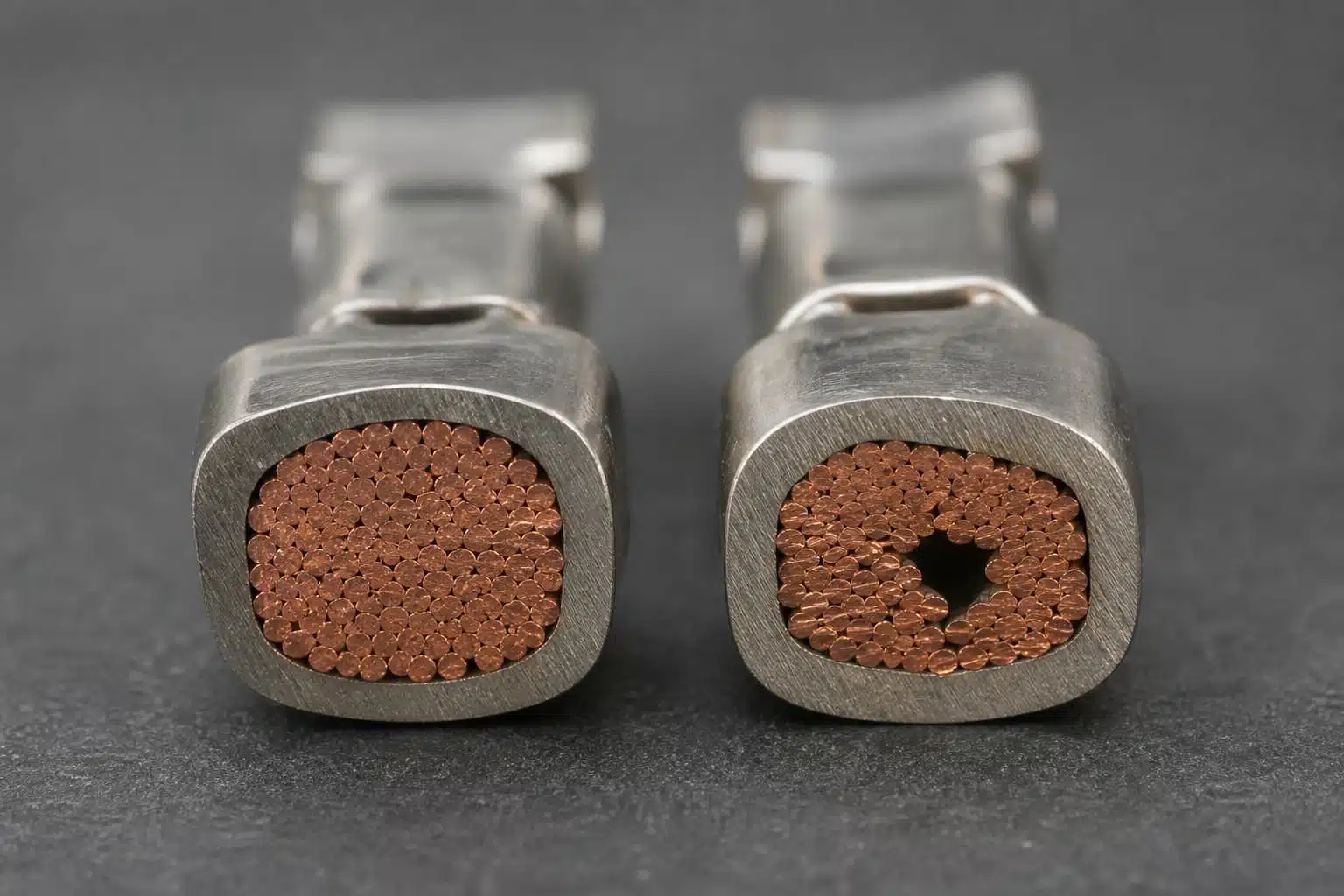
The crimp is where a solar connector meets the cable, and it is the most common starting point for MC4 connector failure. An MC4 bad crimp can look acceptable on the outside and still have high resistance inside.
What goes wrong:
Why it matters: termination resistance sits directly in the current path. When resistance rises, I-squared-R heating builds at the termination, and that heat is what melts housings, discolors contacts, and degrades seals nearby. The melted plastic is usually the effect, not the original defect.
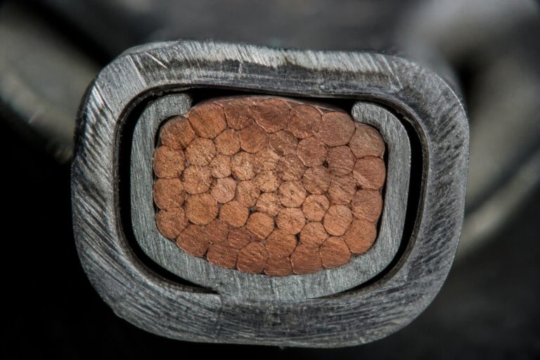
Evidence to collect: crimp geometry against the manufacturer’s acceptance criteria, strand capture and length, pull-test history from the same lot, cross-sections or micrographs where available, tool calibration and maintenance records, and operator and lot traceability. For assembly suppliers, the same records are part of a controlled quality control process.
Practical note: verify the assembly sequence and crimp parameters against the connector and tool manufacturer’s instructions. Do not judge crimp quality by appearance alone — a visually clean crimp can still be electrically poor, and an ugly one can pass.
A contact can be improperly seated even when the two housings appear fully connected, which makes partial mating one of the quieter MC4 connector failure modes. These are two separate checks: internal contact retention inside the housing, and external housing engagement.
What goes wrong:
Evidence to collect: contact position against the manufacturer’s gauge or drawing, lock condition, the exact insertion procedure used on site, and cable routing and strain at the connection point.
A partially mated solar connector reduces contact pressure, raises resistance, and behaves like a loose joint: it runs warm, arcs under load changes, and can appear intermittent long before it fails visibly. When a string drops in and out, check seating before replacing parts.

Sealing depends on a complete, correctly sized assembly — not on the connector alone. Solar connector water ingress usually follows a specific path, and finding the path matters more than drying the part. When moisture is the suspected cause of MC4 connector failure, trace the path before replacing the part.
Potential entry paths:
Two points worth stating plainly. First, an IP67 or IP68 rating applies under defined test and assembly conditions; it is not a guarantee that any two parts will seal. Second, ingress starts a feedback loop: moisture and corrosion raise resistance, resistance raises heat, and heat accelerates the damage that lets more moisture in.
Evidence to collect: orientation of the ingress, cable routing (drips, capillary paths along the cable, or water pooling at low points), and the state of every seal and gland in the chain. Distinguish condensation from external entry — the fix is different.

The conductor and the cable jacket affect different parts of connector performance, and both must suit the connector.
Check ampacity and derating at the system level, considering ambient temperature and grouping. Wrong cable size MC4 assemblies fail because the seal never seats, the conductor runs hot, or both. Do not infer current capability from connector size alone; the datasheet for the exact model, with the exact cable, is the reference.

System incompatibility is a diagnosis in itself. When an MC4 connector failure repeats across different locations with mixed parts, inspect the entire component chain: male and female housings, contacts, seals, caps, cable, and crimp tooling.
Visually similar parts can have different tolerances and different validated combinations. A contact that fits one housing may not seat or lock in another. Mixing manufacturers also means mixing undocumented assumptions about dimensions, material, and test conditions.
Two rules for the diagnosis: treat the connector as a system rather than a single part, and cross-reference the dedicated mixed-connector article for the standards discussion rather than repeating it here. The practical outcome of this failure mode is always the same: replace the mixed set with one approved, documented combination — and verify approvals against the certificates and test documentation for the exact combination before relying on it.
Sometimes the connector is fine, and the operating environment is the problem. MC4 connector overheating in a junction box is often a system-margin issue rather than a part defect. For a closer look at the heating mechanisms behind it, see our [article on why solar connectors overheat or melt ]. Contributors outside the connector itself include:
Distinguish continuous from transient conditions. A short current spike has different effects than hours at high load, and measurements need operating context — a warm connector in a hot, enclosed space is not the same as a warm connector in open air.
Do not apply universal acceptable-temperature values. Use the manufacturer’s limits and the project’s test procedures for the exact connector and cable combination.
Use this sequence when a failure is found. It preserves evidence, separates hypotheses, and gives procurement and training teams something actionable.
1. Make safe and quarantine. Isolate and verify the circuit is de-energized. Quarantine the affected components and do not reuse them.
2. Record the basics. Record the symptom, location, polarity, load history, weather, photos, thermal data, and every marking on the failed part—even when the MC4 connector failure looks obvious.
3. Separate the hypotheses. Divide possible causes into interface, termination, seal, cable, and system-stress categories before concluding.
4. Compare with instructions and records. Check the evidence against the exact assembly instructions and any traceability records for the lot, tool, and crew.
5. Determine scope. Establish whether the problem is one part, one lot, one crew, one tool, one location, or one connector combination.
6. Correct the cause, not just the part. Fix the system-level cause, replace affected components using an approved procedure, and verify the repair.
7. Feed findings back. Close the loop into procurement, training, tooling, and inspection controls so the same failure does not recur.

For manufacturers and cable-assembly suppliers facing repeated MC4 connector failure in the field:
For installers and O&M teams:

A melted housing is evidence, not a full diagnosis. Most MC4 connector failure analysis stops too early, at the part, when the answer lives in the process and the system. Use component, process, installation, and operating data together, and you will find causes that survive scrutiny — and prevent failures, not just replace parts.
If your team is working through a PV connector failure and needs cable-assembly engineering support, send us the application data and failed-part evidence. That includes the connector pair, cable construction, electrical load, environment, and quality requirements. At PVLinkTech, we build controlled solar connector and cable assemblies and are happy to look at the evidence with you.

LET’S BUILD YOUR CONNECTION SOLUTION
Share your application, specifications, and estimated quantity. Our team will recommend a suitable connector solution and provide a quotation.
Low MOQ · OEM & ODM · Product Selection Support · Fast Quote Response