

Need waterproof connectors?Request a Quote →
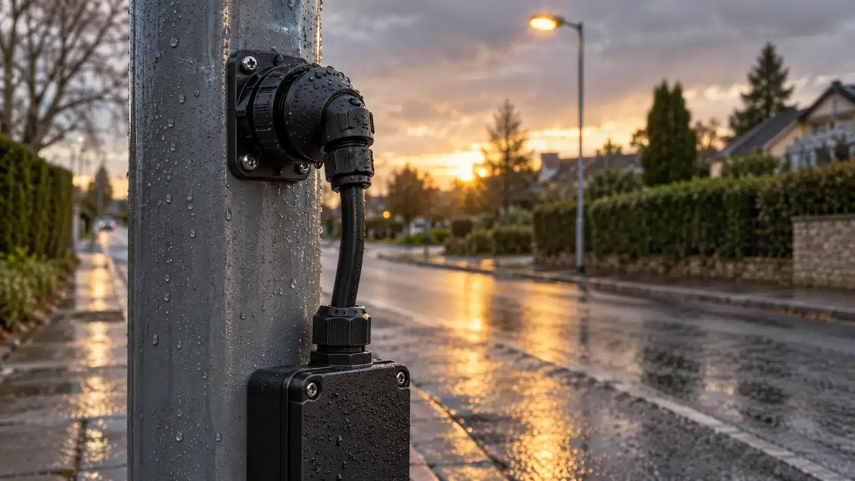
You choose a waterproof DC connector by three numbers first: the system voltage, the continuous current, and the length of the cable run. Get the current or the cable wrong, and a sealed IP68 housing simply protects a connection that still runs hot or delivers too little voltage at the far end.
Two mechanical checks follow, and most spec sheets bury them. The current rating applies per contact, not to the whole connector. The seal is rated for a cable outer-diameter range, not a conductor cross-section. In our experience, a waterproof DC connector project fails at those two points more often than at the seal itself.
Key takeaways
Direct current flows in one direction. An AC arc is helped to extinguish at the current zero crossing, twice per cycle. A DC arc has no such crossing, so a connection that opens under load must interrupt the arc on its own. That difference changes how a rating is written and what it covers.
Steady-state heating is the one place where a waterproof DC connector behaves exactly like an AC one. A DC of 20 A produces the same Joule heating as an AC of 20 A RMS, because the loss is I²R either way. Heat comes from current and resistance, not from the shape of the waveform.
In a 12 V, 24 V, or 48 V system, insulation is rarely the limit. Voltage drop, per-contact current, and the cable-gland interface decide whether the installation works.
Most connector catalogs publish AC ratings, and ours is no exception. The M682 to M685 series is listed at 17.5 A, 24 A, and 32 A at 450 V AC (IEC), with ETL versions at 300 V AC for North America.
Those are AC numbers. A waterproof DC connector selection cannot lean on them for switching duty, and the difference is not the heating.
| Steady-state heating at equal RMS current | Yes | Confirm ambient and cable; I²R is unchanged |
| Insulation and dielectric withstand | Usually, at low DC voltage | Confirm creepage and clearance for the working voltage |
| Contact current rating | Only as a starting point | Rating is tied to test cable, ambient, and a temperature-rise limit |
| Breaking capacity under load | No | DC needs its own rating; no zero crossing to kill the arc |
| Mating or unmating while live | Do not assume | Only where the part is rated for it |
The practical rule: an AC-rated connector can be used on a low-voltage DC circuit as a starting point, but the rating does not transfer to switching duty. If the connector will be opened while carrying current, ask the manufacturer for the DC rating and the test basis. Do not infer it, and do not let a supplier infer it for you.
Start a waterproof DC connector specification with the system, not the catalog. Write down the nominal voltage, the maximum steady-state voltage including charging limits, and whether the circuit is ever switched under load.
On a 12 V or 24 V LED or control circuit, the voltage value sits far below any rating in the catalog. The voltage question then reduces to two things: does the housing keep enough separation between poles, and is the part rated for the way it will be operated? A 48 V DC telecom or battery-auxiliary circuit follows the same logic with a little more margin to confirm.
Voltage becomes the main gate in two cases. The first is a circuit that opens under load, where breaking capacity is a rating of its own.
The second is high-current energy storage. There, system voltage climbs to 1500 V DC and drives creepage, clearance, and touch-safety requirements. The decision method is different and longer, and our 1500 V BESS connector selection guide covers it, including the current profile and cable validation steps a 24 V circuit does not need.
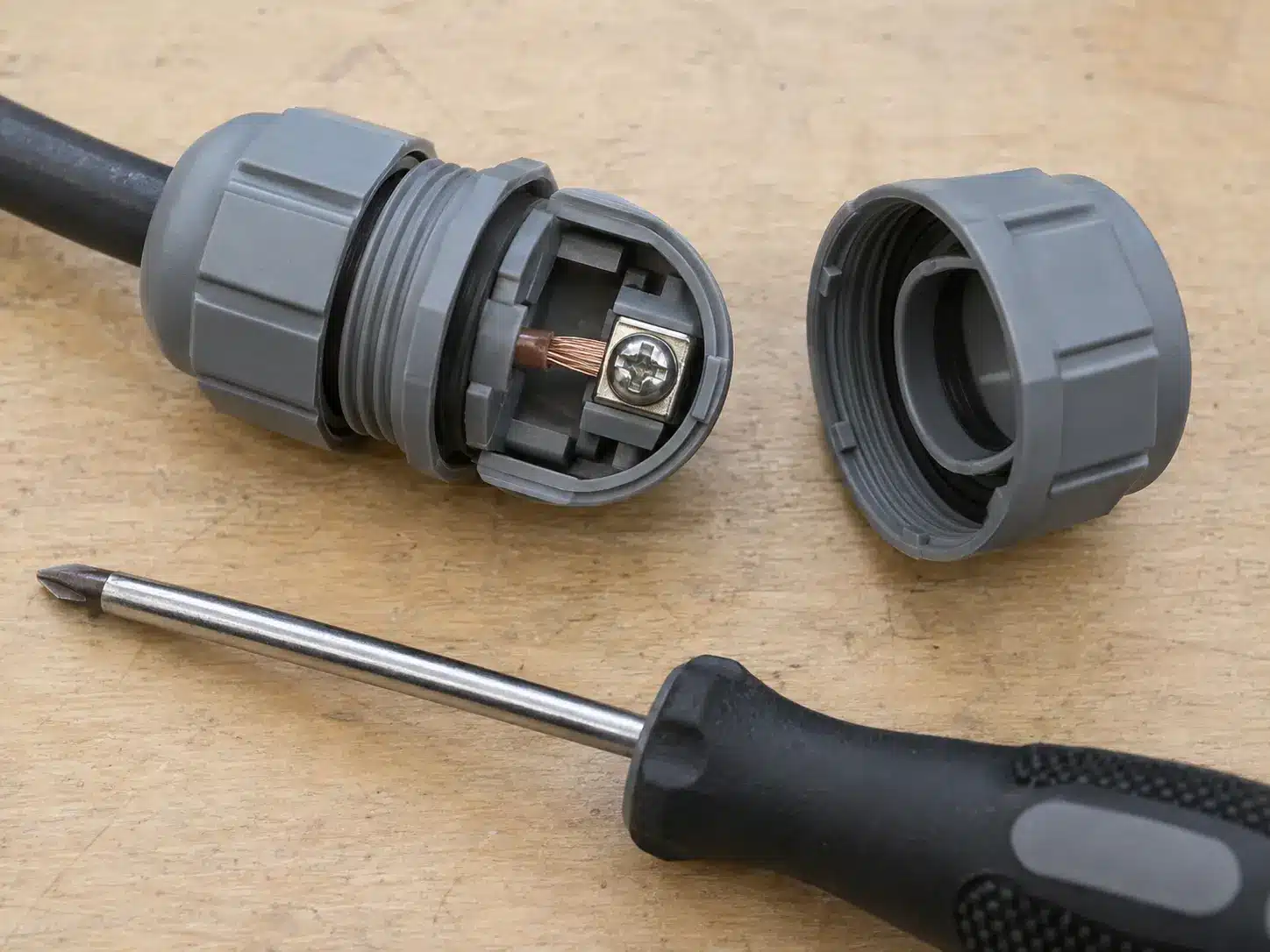
A current rating on a waterproof DC connector datasheet describes one contact under defined test conditions. A 4-pin housing rated 24 A per contact does not carry 96 A. It carries 24 A per contact when every contact, the ambient, and the installed cable match the test setup.
| M682 / M683 | 2–3 | 17.5 A (450 V AC) | 0.5–1.5 mm² |
| M684 | 2–6 | 24 A (450 V AC) / 10 A (ETL 300 V AC) | 0.5–2.5 mm² |
| M685 | 2–5 | 32 A (450 V AC) / 18 A (ETL 300 V AC) | 0.5–2.5 mm² |
The full range, including panel-mount and cable versions, is on the IP68 screw-terminal connector page.
Three adjustments matter before you accept a contact rating as your design current:
This is where heat is decided, and it is worth reading the mechanism rather than the number. Our article on connector temperature rise in high-current DC connections works through the I²R math, contact resistance, and derating with measured examples. The same physics applies at 20 A in a garden lighting run, just with more headroom.
If the connector is multi-pole and the poles carry different duties, treat per-contact current and total current as two separate checks. Our guide to waterproof connector pin count covers how pin allocation affects the housing choice.
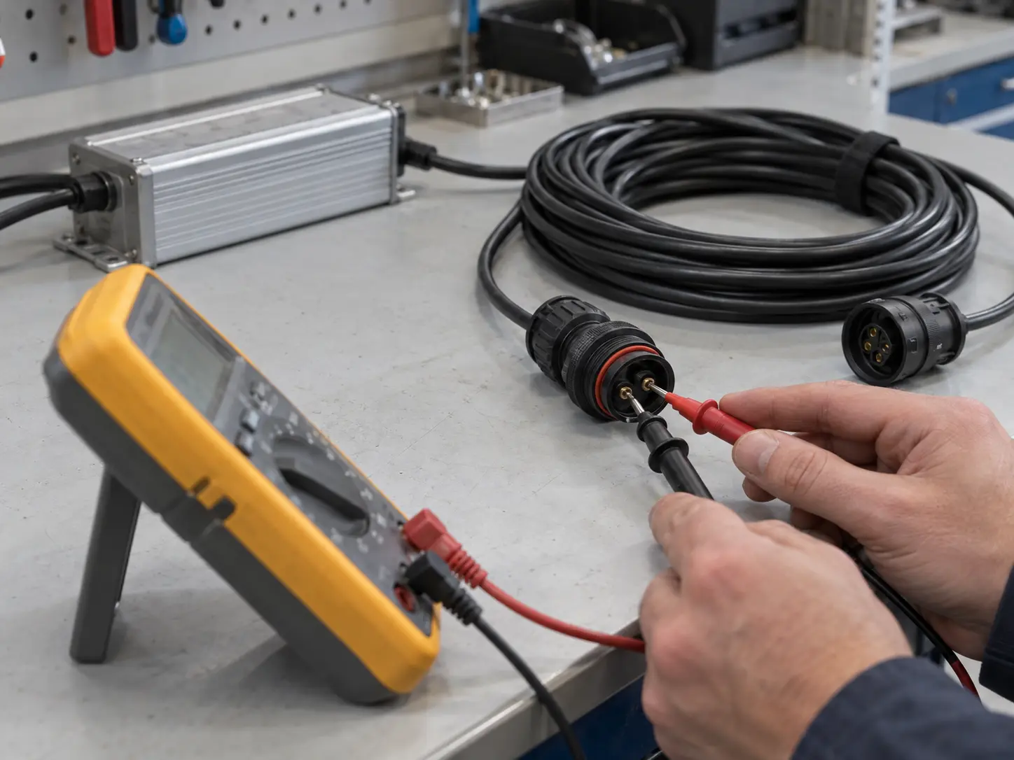
On a 230 V circuit, a 2 V drop is noise. On a 24 V circuit, it is 8% of the supply, and the load at the far end notices. Low-voltage DC is where voltage drop becomes the binding constraint, which is why a waterproof DC connector cannot be chosen before the cable is.
The DC voltage drop of a two-wire run is:
ΔU = 2 × ρ × L × I / A
where ρ is the resistivity of copper (about 0.0175 Ω·mm²/m at 20 °C, rising with temperature), L is the one-way run length in metres, I is the current in amps, and A is the conductor cross-section in mm². The factor of 2 counts the supply and return conductors, because the drop exists in both.
Take a 24 V DC lighting run at 10 A over 20 m one way, on 2.5 mm² cable.
| 24 V | 10 A | 20 m | 2.5 mm² | 2.80 V | 11.7% | 3.36 V | 14.0% |
| 24 V | 10 A | 20 m | 1.5 mm² | 4.67 V | 19.4% | 5.60 V | 23.3% |
| 24 V | 10 A | 20 m | 4.0 mm² | 1.75 V | 7.3% | 2.10 V | 8.8% |
| 12 V | 5 A | 10 m | 1.5 mm² | 1.17 V | 9.7% | 1.40 V | 11.7% |
| 48 V | 16 A | 30 m | 4.0 mm² | 4.20 V | 8.8% | 5.04 V | 10.5% |
Turned around, the same math gives the longest run a given cable supports:
| 24 V, 10 A, 2.5 mm² | 5.1 m | 8.6 m |
| 12 V, 10 A, 2.5 mm² | 2.6 m | 4.3 m |
| 48 V, 16 A, 4.0 mm² | 10.3 m | 17.1 m |
Two points come out of that table. A 12 V system reaches its drop limit at a fraction of the distance a 48 V system does on the same cable. Hot conductors also drop more than cold ones, so a design that just passes at 20 °C can fail in a summer enclosure.
Common design targets are 3% and 5% of nominal voltage. The value you must meet comes from your project or client specification. Installation codes set their own limits and differ between countries, so confirm the number before sizing.
Ampacity is the second gate, not the first. Ampacity is the maximum current a conductor carries continuously without exceeding its temperature rating, and it depends on the insulation rating, ambient temperature, grouping, and installation method. On a short, high-current 24 V run, ampacity decides the size. On a long low-voltage run, voltage drop usually decides it first.
The same confusion turns up in the field. A DIY Solar Power Forum thread on waterproof connectors opens with three questions — ampacity, maximum voltage, and how to pick a pin for a given gauge — and the replies note how many budget connectors ship with no published rating at all. That is a community anecdote, not evidence, but it shows the gap a datasheet is supposed to fill.
Wire size may be called out in mm² or in AWG. The metric standard IEC 60228 defines conductor cross-sections directly in mm². AWG is the North American system, and it is not a straight conversion, so check both the area and the strand construction against the terminal range before ordering.
A waterproof DC connector seals on the outside of the cable, not on the copper. The gland compresses an elastomer against the cable jacket, so the number that decides whether the seal works is the jacket outer diameter.
Conductor cross-section and cable outer diameter are independent numbers. A 2.5 mm² cable can measure around 4 mm across with thin insulation, or well over 8 mm with a thick jacket and a screen. Both are “2.5 mm²” cables. Only one of them may sit correctly inside a given gland.
Our M682 to M685 series covers cable outer diameters from 3 mm to 14 mm across the range. Within that envelope:
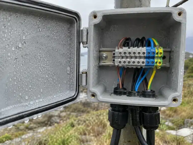
Where the run needs a splice point rather than a connector pair, the same rule applies inside the box: cable entries are the leak path. Our IP68 waterproof junction box range lists entry configurations from one-way to multi-way, all rated for 0.5–2.5 mm² conductors.
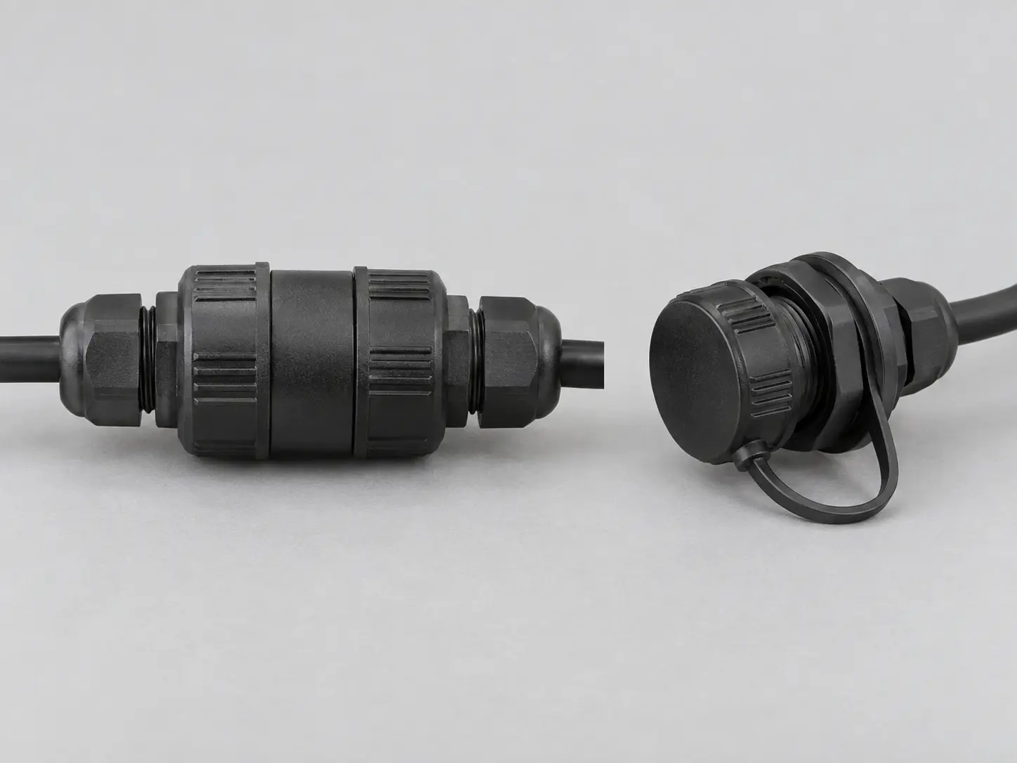
The IP code comes from IEC 60529. The second digit describes water ingress under defined test conditions, and for IP68 the depth and duration are agreed between manufacturer and user. The rating is not a single universal number.
For the M682 to M685 series, the IP68 claim applies to the complete assembled connector: housing mated, gland tightened, tested at 2 m immersion for 120 hours. Two consequences follow.
First, the rating describes the assembly, not the part on the shelf. An unmated socket is an open cavity with exposed contacts. Cap it, or plan the installation so no socket stays open.
Second, IP68 covers immersion and says nothing about jets or washdown. A connector that survives continuous immersion is not automatically rated for a pressure washer aimed at the housing joint. Our comparison of IP67 and IP68 waterproof connectors sets out the two test regimes; if the equipment gets washed down, that is the requirement to check.
Condensation is the quiet third path. A sealed enclosure that heats and cools each day can pull moisture in through the cable entry, or trap what was already inside. Venting, desiccant, or a drain path may belong in the design even when the connector is perfectly sealed.
A waterproof DC connector selection ends with a short test plan, not with a part number. Five checks cover most field risks on a low-voltage DC installation:
On a high-volume build, the assembly method matters as much as the part. A screwless termination removes the torque variable and shortens cycle time on the line, which is why the M684-T and M684-X use push-in terminals. The trade-offs are explained on the screwless waterproof connector page.
PVLinkTech runs specification review, material checks, assembly inspection, and final verification before dispatch, with inspection records available on request for the relevant model. Our quality control page describes what each stage covers.
Use this table to find the binding constraint for a project before you open a catalog.
| 12/24 V LED, signage, landscape lighting, long run | Voltage drop | Conductor size for target drop at worst-case temperature | M684 / M685 |
| 24/48 V power feed, 20–30 A, short run | Per-contact current and terminal capacity | Conductor cross-section against terminal range | M685 |
| Mixed power and control in one housing | Contact count and pole separation | Pin allocation and housing size | M684 (up to 6 pins) |
| Splice point in a buried or wet run | Cable entry sealing | Jacket OD against entry range | IP68 junction box |
| Connection opened while carrying current | DC breaking capacity | Request the DC rating and test basis | Confirm per project |
| Washed-down equipment | Jet or washdown protection | IPX5/IPX6 or IPX9K rating, not IP68 alone | Confirm per project |
The catalog covers these cases with 2 to 6 poles, 17.5 A to 32 A per contact, and cable outer diameters from 3 mm to 14 mm. The full waterproof DC connector range, with drawings and terminal options, is listed on the product page.
These five cases come up again and again when a waterproof DC connector is bought on a headline number instead of a calculation.
| AC rating used as a switching rating | Arc damage or welded contacts when the connector is opened under load | Request the DC breaking rating, or isolate the circuit before opening |
| Current rating read as total, not per contact | Contacts run above their rated current; housings discolor and seals soften | Sum the current per contact and compare each against the rating |
| Cable chosen to fit the terminal, not the run | Load undervoltage at the far end; the supply looks faulty but the cable is | Size for voltage drop at the hottest conductor temperature |
| Jacket OD outside the gland range | Water tracks past the seal; corrosion follows the strands | Record jacket OD per model and confirm the accepted window |
| IP68 assumed for an open socket | Wet contacts, oxidation, intermittent faults on the next service visit | Cap unmated sockets or redesign for mated-only exposure |
One more failure mode hides in the same family: a joint that was never tested at the extremes. A seal that passes at the nominal cable diameter and fails at the thin end, or a termination that holds at 25 °C and drifts at 60 °C, is the same mistake in different clothing.
Practical answers to common questions about voltage, current, cable sizing, IP ratings and waterproof connector selection.
Start from the maximum steady-state voltage of the system, including charging limits, then ask two questions. Is the part ever opened while carrying current? If yes, you need a DC breaking rating. If no, confirm the insulation, creepage, and pole separation for your working voltage. On 12–48 V DC circuits, current and voltage drop are usually the harder constraints.
As a starting point, yes, it is common practice on low-voltage circuits that are not switched under load. The AC rating does not automatically convert to a DC rating, though. Confirm the DC rating and the test basis with the manufacturer if the circuit is opened under load, or if a standard applies to your market.
Whichever binds first, and you have to check both. Long low-voltage runs are normally limited by voltage drop, so the cable ends up larger than ampacity alone would require. Short runs at higher current are normally limited by ampacity, ambient temperature, and bundling. Run the drop calculation first, then confirm the result against your insulation rating and installation method.
Per contact, under defined test conditions. A 4-pin housing rated 24 A per contact does not carry 96 A. Each loaded contact carries its own current and generates its own heat. The M682 to M685 figures are established with all contacts loaded, so adjacent-contact heating is already included. All contacts can be loaded at once; the ambient temperature check still applies.
It depends on the model, not on the conductor size. The M682 to M685 series covers jacket outer diameters from 3 mm to 14 mm across the range. Treat that as the family envelope: confirm the accepted window for the exact model you are ordering before you commit the cable. A cable thinner than the accepted minimum leaves the seal without compression, however tight the gland feels.
No. Our IP68 rating applies to the complete assembled connector: mated, with the gland tightened, tested at 2 m immersion for 120 hours. An unmated socket has an open cavity and exposed contacts. Fit a cap where an interface stays open, or plan the installation so the connector is never left exposed.
Not directly. Heat comes from current and resistance: I²R at the contact, the termination, and the conductor. A 24 V connector at 20 A runs as warm as a 48 V connector at 20 A. Voltage drives insulation, creepage, and clearance requirements, plus the arc question if the circuit opens under load. Keep the thermal check and the voltage check separate.
Send the system voltage and its maximum steady-state value. Include the continuous and peak current per contact, the one-way run length, cable construction including conductor cross-section and jacket outer diameter, ambient temperature inside the enclosure, whether the connector is mated and unmated in service, and the required IP rating together with its operating conditions and annual volume.
Send PVLinkTech the system voltage, the current per contact, the run length, and the cable construction you plan to use. We will check the numbers against the M682 to M685 range, confirm the cable outer diameter against the gland, and tell you if the part you asked about is wrong for the duty.
Standard models are available as 1-piece evaluation orders, with production runs from 100 pieces. When a project needs a different pole count, terminal style, or a complete cable assembly, the same engineering review applies — our custom waterproof connector manufacturing process covers how those builds are quoted.
Request a waterproof DC connector and cable review →

LET’S BUILD YOUR CONNECTION SOLUTION
Share your application, specifications, and estimated quantity. Our team will recommend a suitable connector solution and provide a quotation.
Low MOQ · OEM & ODM · Product Selection Support · Fast Quote Response