

Need waterproof connectors?Request a Quote →
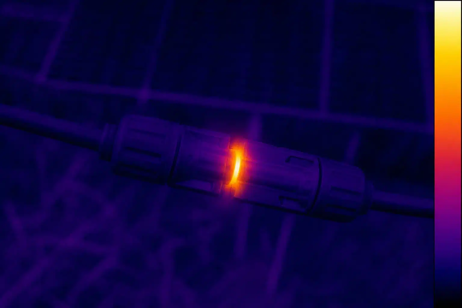
A melted MC4 connector does not always trip the breaker. In many cases, the solar string continues producing power even though the connector housing has melted or the contact has become discolored.
This usually indicates a high-resistance connection, not an overcurrent fault. A loose, contaminated, partially mated, or poorly crimped contact creates resistance at one point in the circuit, producing a localized PV connector hot spot.
Because the total circuit current remains below the breaker’s trip threshold, the breaker stays closed. This article explains why MC4 overheating occurs, how to inspect the damage, and which components should be replaced.
PV strings can remain energized whenever they are illuminated. Before any inspection, disconnection, or repair, isolate the affected circuit, follow the site’s approved lockout/tagout procedure, verify that the circuit is de-energized with an appropriate DC meter, and use qualified personnel with the required PPE.
This article does not describe live-work procedures.
A melted MC4 connector usually traces back to excessive resistance at one of two locations: the cable crimp or the connector’s mating interface.
A connector is never a perfect conductor. Every crimp and every pin-and-socket interface has some contact resistance, which is why current ratings depend on cable size, ambient temperature, and assembly quality. In a properly assembled connector, that resistance is small, and so is the heat.
The trouble starts when the resistance goes up. Heat generated at a resistance R carrying current I is I²R (Joule heating), and current in a series circuit is the same everywhere: the cable, the module, and the breaker all see normal current while the joint acts as a small heater. Doubling the joint resistance doubles the heat at the same current; halving the effective contact area does the same. There is no fixed current at which a bad joint melts; a connector rated for 30 A can overheat on a string drawing far less if the joint resistance is high enough.
The practical point: a connector can overheat below its rated current, and the damage shows at the joint first, not at the breaker or the module.
Contact resistance is the resistance at the mechanical interfaces in the current path: where the conductor meets the terminal inside the crimp, and where the pin meets the socket when mated. Good design and assembly keep it low; dirt, corrosion, a loose crimp, partial mating, or a contact that has lost spring force all push it up. The heat that melts plastic housings is generated exactly where that resistance sits, and the rest of the circuit stays cool.
A breaker is an overcurrent device. Its job is to open the circuit when the current exceeds its rating long enough to risk damage to conductors and equipment. The key word is current. A melted MC4 connector is often mistaken for a breaker failure, but the breaker may have operated exactly as designed. A high-resistance connection does not raise the current; in a series circuit, it slightly reduces it, because the added resistance opposes the flow. The breaker therefore sees normal or slightly low current and stays closed, even while the joint approaches temperatures that soften plastic and degrade seals.
The same reasoning applies to fuses. A fuse clears on overcurrent, and a bad connector does not produce overcurrent. If the joint degrades to the point of arcing, the arc current can be erratic and may stay below the trip threshold, which is why arc-fault protection, where fitted, is a separate layer rather than a substitute for connector inspection. The protection scheme protects the cable and equipment from overload. It was not designed to detect a hot joint, and no breaker setting can make it do so.
Terms that carry the argument: overcurrent protection opens the circuit when current exceeds a rating; it measures current, not temperature. Contact resistance is the resistance at the conductor-to-terminal and pin-to-socket interfaces. I²R (Joule) heating is heat generated by current through resistance, and it concentrates at high-resistance joints. A series circuit means all elements carry the same current, so a local resistance does not raise the current anywhere else.
The damage marks on a melted MC4 connector help determine which components must be replaced, so inspect them carefully before starting the repair.
A crimp-zone failure means the heat was generated where the terminal meets the conductor: an incomplete crimp, the wrong die, a conductor not fully inserted, or one undersized for the current. The damage concentrates at the cable entry, with a discolored terminal and melted insulation near the crimp.
A mating-interface failure means the heat was generated between pin and socket: partial mating, contamination, or two halves never validated as a pair. The damage sits at the mating face, with a deformed locking area and burn marks between the contacts.
Corrosion is usually a symptom of an ingress path: a failed seal, a wrong cable diameter, a cracked housing, or an uncapped connector. Partial mating deserves special attention because it can look connected from outside while the contacts barely touch, so check the lock, not just the alignment.

| Where the damage sits | What it usually points to | What to verify |
|---|---|---|
| Cable entry, melted insulation near the crimp, discolored terminal | Termination problem: bad crimp, wrong die, undersized conductor | Crimp geometry against manufacturer spec, conductor size, strip length |
| Mating face, deformed locking area, burn marks at pin and socket | Mating-interface problem: partial mating, contamination, incompatible halves | Lock engagement, contact condition, part numbers of both halves |
| Corrosion, green residue, moisture inside the housing | Ingress path: failed seal, wrong cable diameter, cracked housing | Seal condition, cable jacket OD, entry path |
| Locking tabs not fully engaged, visible gap | Partial mating or damaged lock | Mating procedure, lock condition |
The full root-cause list, including cross-mating, disconnection under load, and mechanical stress, is covered in our solar connector overheating causes article; this page stays on the breaker question and the replacement boundary.
If you found a melted connector, do not cool it, tighten it, or push it back together while the circuit is live. Isolate first, in this order.
Open the string isolator or disconnect the inverter input according to the system design, and do not assume the breaker is the only disconnection point. Verify zero voltage with an appropriate DC meter at the connector before touching it; PV strings can remain energized in daylight even after one disconnection point, depending on topology. Use qualified personnel and the required PPE, and keep the connector for photos rather than discarding it; the evidence is worth more than the part.
Two boundaries. This article does not describe live-work procedures; if the system cannot be safely isolated, stop and get qualified help. And a melted connector is not a candidate for cleaning or remating; heat damage compromises the housing, the seal, and the contact, so the repair is replacement, not reconditioning.
When investigating a melted MC4 connector, follow the steps below after the affected circuit has been safely isolated.Each step narrows the answer; none of them alone is enough.
| Step | What to do | What it tells you |
|---|---|---|
| 1. Photograph | Record string number, connector position, markings on both halves, damage from every angle | Evidence for diagnosis and replacement review |
| 2. Visual check | Identify which zone melted; look for corrosion, a gap at the lock, a cracked housing | Points to termination, mating, or ingress |
| 3. Pull test | Gently tug each cable at the connector; check for movement at the crimp or in the housing | Confirms a loose termination or a backed-out contact |
| 4. Resistance check | Measure across the pair with a milliohm meter; compare with a known-good assembly or the manufacturer’s specification | Quantifies the joint resistance |
| 5. Thermography | With the system under load, scan the string and compare connector temperatures | Finds hot joints, including ones not yet visibly damaged |
| 6. Check the neighbors | Inspect connectors with the same installation history | A single failure is often part of a batch problem |
One boundary on the measurements: they describe the joint’s current state, not why it degraded. Pair the numbers with the visual evidence and, where available, the installation records. And a normal reading on a cooled connector does not clear it; visible heat damage is failure, whatever the meter says now.

If the housing is deformed, discolored, cracked, or arced, replace the complete pair and do not reuse either half. Do not simply cut off the damaged end and crimp a new contact onto the same cable unless the insulation and conductor are intact; heat travels along the conductor, so check for blistered insulation and discolored strands and cut back to clean conductor when in doubt. If the failure is inside a junction box or combiner box, inspect the busbar, fuse holder, and neighboring terminations for heat damage before closing it up.
Replace the pair, not the half. The two halves form one matched interface and carry the same current; replacing one side leaves a mixed pair whose mating behavior has not been validated. Use a matched PV connector pair from the same manufacturer and model, and verify intermatability documentation before mixing brands; appearance alone does not prove compatibility.
Use the manufacturer’s crimp tool and die for the exact contact and conductor; the crimp is where most of these failures start. Follow the assembly instructions for strip length, insertion depth, and lock verification. Mate fully; you should feel the click, and the locking tabs should sit flush. Keep unmated connectors capped and dry. Run a thermography pass in the first months after commissioning, because hot joints announce themselves early. Buy traceable, certified components; nonconforming and counterfeit parts are a documented source of failures. Record part numbers and installation dates; that record is half of the next diagnosis.
Send us the failed connector model and photos for a preliminary replacement review . We can help confirm the mating combination and the replacement scope before you order; include the markings on both halves, the cable size, and a photo of the damage if you have one.
Request a Replacement ReviewRelated resources

LET’S BUILD YOUR CONNECTION SOLUTION
Share your application, specifications, and estimated quantity. Our team will recommend a suitable connector solution and provide a quotation.
Low MOQ · OEM & ODM · Product Selection Support · Fast Quote Response