

Samples in stock · Response within 12 hours. Request a Quote →
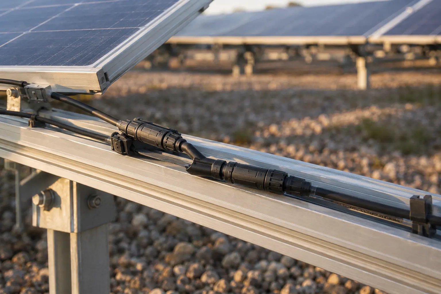
An MC4 Y branch connector parallels two strings at the array instead of routing them to a combiner box. Whether that is allowed is a fault-current question before it is a cost question, because a Y branch carries no fusing and cannot be opened under load. It is only appropriate where the paralleled conductors can survive the current the neighbouring strings can feed into a fault. Work that out first, and the choice between a branch connector and a combiner box usually makes itself.
A Y branch suits two strings, where the design current stays inside the connector rating and the code you are inspected to permits paralleling without per-string protection. A combiner box takes over as soon as three or more strings are paralleled, where each string needs overcurrent protection, or where the array needs a disconnect point or monitoring. The crossover sits around the second to third string, and it is set by fault current rather than by array size.
| Term | What it means here |
|---|---|
| Branch connector | Paralleled connectors at the array, one input splitting into two outputs or the reverse |
| String | A series run of modules whose voltage adds and whose current does not |
| Isc | Short-circuit current of one string, from the module datasheet |
| Back-feed | Current a faulted string receives from the parallel strings |
| Continuous-duty factor | The multiplier a code applies to Isc when sizing conductors and protection, commonly 1.25 |
| Combiner box | An enclosure with per-string protection, and usually a disconnect |
The electrical difference between the two is simple to state. A branch connector is a mechanical joint that happens to parallel two circuits. A combiner box is a protective device that also happens to parallel them, and the rest of the comparison follows from that difference.
Configurations vary with the array. A common form of MC4 Y branch connector splits one input into two outputs, used where a single home-run cable serves two paralleled strings. The reverse, two inputs combining into one output, appears where two strings land on one cable running to the inverter. Which one you need is decided by where the paralleling happens, not by the connector itself, and the pole and keying arrangement has to match the rest of the string.
In a single string, a short circuit is fed by the string’s own Isc. On a modern module that is around 13.5 A, and the module leads and connector are built to carry that current without difficulty.
Parallel two strings and the arithmetic changes. If one string faults, the healthy string feeds current into the fault as well as contributing its own. With three strings, the other two feed the fault. The faulted conductors now have to carry that combined current, and they were sized for one string.
| Strings in parallel | Combined Isc | Back-feed into one faulted string |
|---|---|---|
| 1 | 13.5 A | none |
| 2 | 27.0 A | 13.5 A |
| 3 | 40.5 A | 27.0 A |
| 4 | 54.0 A | 40.5 A |
This is why most PV installation codes require overcurrent protection on each string once three or more are paralleled. A fuse interrupts the back-feed before the faulted conductor is damaged. Fuses need a place to live, and that place is a combiner box. A Y branch has nowhere to put them, which is the whole reason the two products exist side by side rather than one replacing the other.
For two strings, protection is often not required, provided the conductors can carry the total available fault current. That condition has to be verified against the module datasheet and the code that applies, not assumed, and it is the single check that decides whether a Y branch is permitted at all.
Where protection is required, its rating comes from the module rather than from the connector. Each module datasheet publishes a maximum series fuse rating, typically in the 15 to 25 A range on modern modules, and that figure sets what the string protection has to be. A connector rated above the module’s fuse rating does not remove the requirement. It only means the connector is not the limiting component.
| If the situation is | Use | Why |
|---|---|---|
| Two strings, conductors verified for fault current | Y branch | No protection required, no enclosure to mount |
| Three or more strings | Combiner box | Per-string fusing required, nowhere else to put it |
| Two strings but a disconnect is specified | Combiner box | The enclosure carries the disconnect |
| Rooftop or floating, weight is critical | Y branch, if permitted | Removes an enclosure and its mounting hardware |
| Local code requires per-string protection | Combiner box | Code requirement, not a preference |
| Combined current above the connector rating | Re-design | See the sizing calculation below |
A branch connector adds two mated pairs where there was one joint. Both are contact interfaces with their own resistance, and both are points where a partially engaged half can go unnoticed. That is not a reason to avoid the part, but it does raise the installation discipline around it: each pair has to be fully latched, and the assembly needs support so the weight of the cables does not pull on the joints.
A combiner box moves the joints inside an enclosure, where they are protected and can be inspected. It also needs a mounting point, a gland per cable, and clearance for the door to open. On a rail-mounted rooftop array, that mounting point is sometimes the thing that decides the layout.
The saving from a branch connector is real at the home run. Paralleling at the array halves the number of cables returning to the inverter, and on a long DC run that reduces both copper and voltage drop. Where the array already sits close to the inverter, the saving is small and the enclosure is the simpler build.
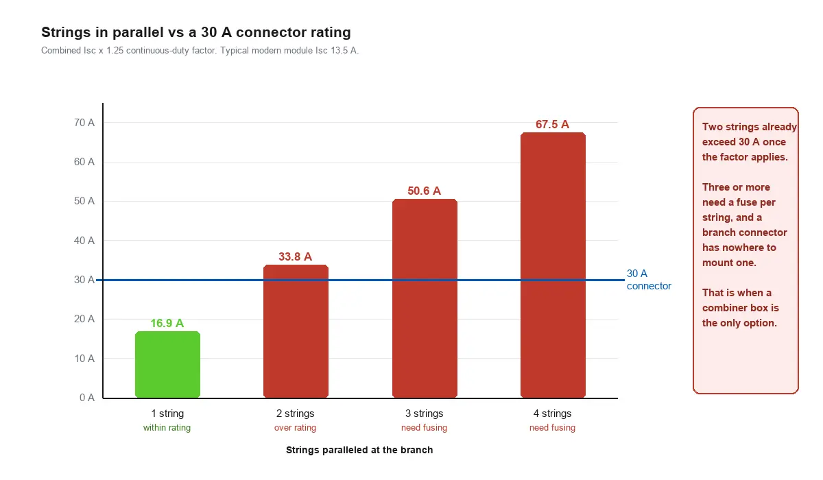
Adding up Isc is not enough. Conductors and protection are sized on Isc multiplied by a continuous-duty factor, commonly 1.25 in PV circuits, because a module can sit at or above its rated output for hours.
| Strings in parallel | Combined Isc | After a 1.25 factor | Fits a 30 A connector? |
|---|---|---|---|
| 1 | 13.5 A | 16.9 A | Yes |
| 2 | 27.0 A | 33.8 A | **No** |
| 3 | 40.5 A | 50.6 A | No |
| 4 | 54.0 A | 67.5 A | No |
The second row is the one worth reading twice. Two strings of a modern 13.5 A module come to 33.8 A once the factor is applied, which is already above a 30 A connector rating. That does not automatically prohibit an MC4 Y branch connector in every jurisdiction, because the factor applied to a connector is not identical everywhere, but it does mean the assumption that the part comfortably handles two modern strings is wrong often enough to be worth checking every time. Older modules with lower Isc left more headroom, and a lot of field practice was learned on those.
For background on how protection is applied to DC circuits generally, see the overcurrent reference. If your two-string case lands close to or above the rating, the honest options are a lower-current module configuration, a larger branch assembly, or a combiner box. Adding a bigger connector to a branch that the rest of the string cannot match does not help.
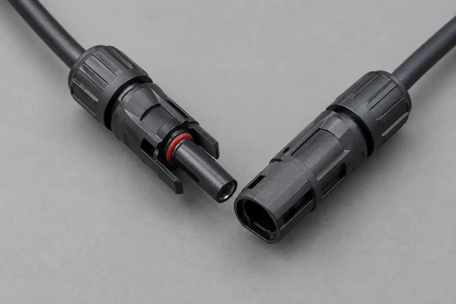
Whether you are buying a branch connector or specifying a combiner box, the same information drives the quote:
Branch assemblies are produced as a project item rather than held as a catalogue part, because the configuration depends on the array. That suits the way arrays are actually specified, but it does mean the string data has to be supplied before the part can be confirmed. Our custom connector process covers how a project like this runs, from DFM review through sample validation, and the MC4 solar connector page gives the ratings of the connector family these assemblies are built from.
It parallels two PV strings at the array, replacing one combiner box and its fuses where the paralleling is permitted without per-string protection and no disconnect is required at that point.
Generally no. Once three or more strings are paralleled, most codes require overcurrent protection on each string, and a branch connector has no place to mount a fuse. That points to a combiner box.
Check whether the conductors can carry the total available fault current, applying the continuous-duty factor your code requires, and confirm against the module datasheet and local requirements. It is a verification, not a rule of thumb.
Because PV circuits can sit at or near rated output for hours, code sizing applies a multiplier, commonly 1.25, to Isc. Two modern 13.5 A strings come to 33.8 A after that factor, which is above a 30 A connector rating.
They reduce the number of home-run cables by paralleling at the array, but they do not remove the need for protection where it is required, so the saving applies only to the permitted two-string case.
Yes, and they are produced to the array rather than as a stocked catalogue item, so the configuration is confirmed against the string count, module data and conductor size before the part is quoted. Certification documents for the connector family are in our certificates section.
Send us the string count, module Isc, maximum series fuse rating, system voltage and conductor size, and we will confirm the configuration, tell you whether the paralleling is suitable for a branch assembly or needs a combiner, and arrange samples for validation.
Request a Quote
LET’S BUILD YOUR CONNECTION SOLUTION
Share your application, specifications, and estimated quantity. Our team will recommend a suitable connector solution and provide a quotation.
Low MOQ · OEM & ODM · Product Selection Support · Fast Quote Response