

Samples in stock · Response within 12 hours. Request a Quote →
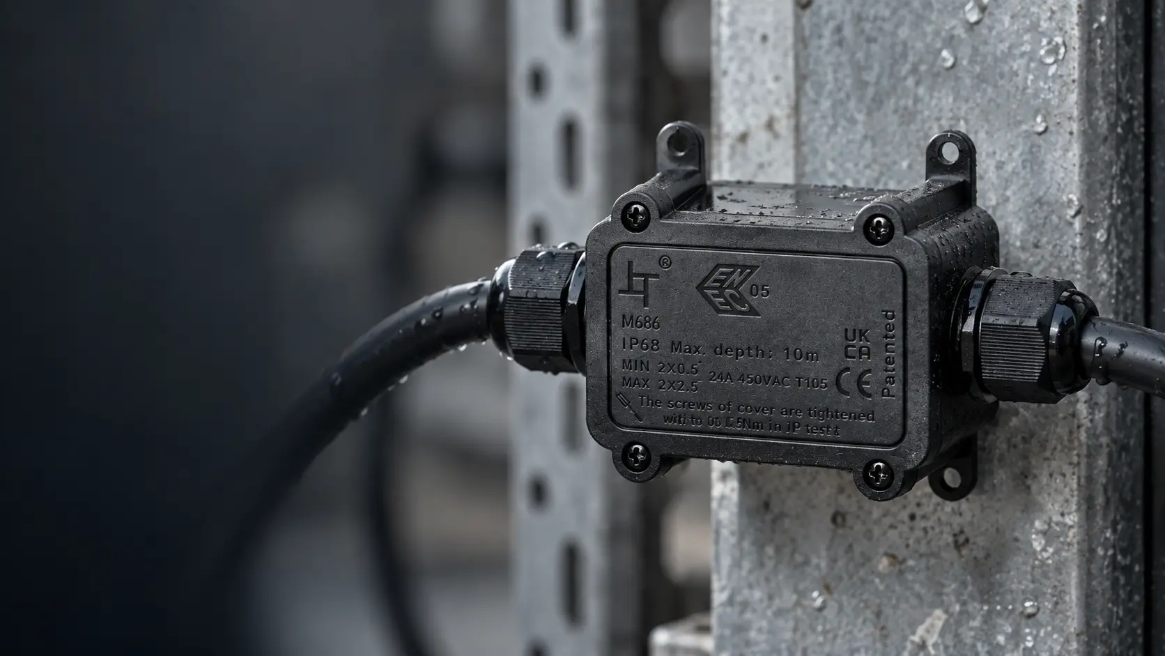
A waterproof connector for multiple wires solves a different problem from an ordinary two-pole connector. The joint has to carry more than one circuit, or split one feed across several outputs, without opening a path for water to follow. The product family that fits is usually obvious once you know three things: does the joint stay permanently sealed, does someone have to open it later, and how many cables actually enter the shell.
| Term | What it actually means |
|---|---|
| Pole / pin | One electrically isolated circuit inside the connector shell |
| Way | A separate cable entry into a junction box, not a separate circuit |
| Multi-pole connector | Several isolated circuits in one sealed shell, one cable per side |
| Splitter | One input distributed to two, three, or four outputs |
| Re-enterable joint | Can be opened and re-terminated without cutting the cable |
| Mated IP rating | Applies only when the two halves are fully engaged |
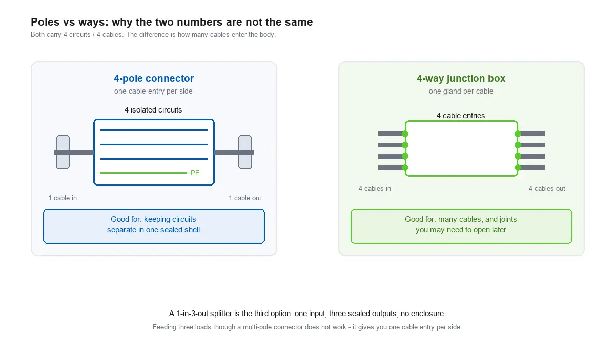
Poles and ways are the easiest pair to order the wrong way round. A 4-pole connector carries four circuits through a single cable entry on each side. A 4-way junction box accepts four separate cables. They are not substitutes, and a waterproof connector for multiple wires ordered on the wrong one of those two numbers will arrive unusable for the job.
| Method | Best when | Suitable families |
|---|---|---|
| Multi-pole connector | 2–6 circuits that must stay isolated, one cable each side | M684 (24 A), M685 (32 A) |
| Splitter connector | One feed distributed to 2–4 branches, sealed inline | M685 splitters, 1-in-2/3/4-out |
| IP68 junction box | Five or more cables meet, or the joint needs service access | M686 (2-way to 14-way) |
| Push-in connector or terminal block | Repeated terminations inside a panel or enclosure | 863, 861, 840, PA terminal blocks |
This is the family most people mean by a waterproof connector for multiple wires. The shell seals once, and each pole stays electrically independent inside it, which matters when circuits must not touch: separate lighting circuits, a control pair alongside a power pair, or a protective conductor that must not share a pole.
| Series | Poles | Current | Voltage | Conductor | Cable OD |
|---|---|---|---|---|---|
| M682 / M683 | 2–3 pin | 17.5 A | 450 V AC (IEC) | 0.5–1.5 mm² | 3–6.5 mm, 5–9 mm / 5–10 mm, 7–12 mm |
| M684 | 2–6 pin | 24 A | 450 V AC (IEC) · 10 A / 300 V AC (ETL) | 0.5–2.5 mm² | 4–8 mm, 7–12 mm |
| M685 | 2–5 pin | 32 A | 450 V AC (IEC) · 18 A / 300 V AC (ETL) | 0.5–2.5 mm² | 4–8 mm, 8–12 mm, 10–14 mm |
All three are rated IP68 and operate from −40 °C to +105 °C. The screw waterproof connector range covers M682 through M685 in detail, including the M684-T and M684-X variants that use screwless terminals, and the cable-to-board models for wiring inside a luminaire or driver housing.
Two details decide whether this family works on a given job. Pole count is a ceiling rather than a target, so leaving a pole unconnected is fine but putting two circuits on one pole is not. The current rating that governs approval may also be the lower of the two published figures: the M684 and M685 are rated 24 A and 32 A under IEC, and 10 A and 18 A under ETL at 300 V AC. Choose against the standard your project is inspected to.

When the job is distribution rather than isolation, a splitter keeps the joint inline and sealed with no enclosure to mount. The M685 splitter variants break one input into two, three, or four outputs at the same 32 A and IP68 ratings as the standard series, and are the right answer when a single supply point has to serve several luminaires along a run.
The family covers 1-in-2-out, 2-in-2-out, 1-in-3-out, and 1-in-4-out configurations. Those two numbers describe inputs and outputs, not poles, so the model code has to be read against your circuit rather than against the pole count. Feeding three luminaires through a multi-pole connector does not work, because a multi-pole shell gives you one cable entry per side; three output cables need three connectors or a splitter.
The trade-off against a junction box is access. A splitter is a permanent in-line assembly; if the branch wiring is likely to change, the box is the better choice.
Once five or more cables meet, or when someone will need to open the joint during the installation’s life, an enclosure takes over from a connector. The IP68 waterproof junction box range runs from 2-way up to 14-way, with gland ranges covering 3–6 mm to 10–14 mm cable, so each incoming cable is sealed at its own entry rather than sharing a multi-pole shell.
A junction box in the general electrical sense is described in the junction box reference; the M686 range adds sealed glands at each cable entry so the enclosure itself can sit outdoors. The trade between the two families is simple: a box gives you access and more cable entries, while a connector gives you a smaller, cheaper joint that stays sealed. Specifying a box only because it accepts more cables usually means paying for re-entry the installation never uses.
Inside an enclosure, the sealing problem moves from the cable joint to the enclosure itself, and the priority becomes repeatable, fast termination. Push-in connectors such as the 863 series (16 A, 450 V AC), 861 (24 A), and 840 (32 A) accept solid and stranded conductors and are re-openable without tools, while the PA terminal block range covers 1 to 12 positions at 17.5–24 A and can be cut to length. The tool-free wire connector article covers how the push-in mechanism works, including the cases where it is the wrong choice.
These are enclosure-side products. The environmental protection comes from the enclosure they sit in, not from the terminal itself, so they are not an outdoor substitute for an IP68 connector. The terminal range also decides how much rework is possible later: a push-in connector releases a conductor in seconds, while a crimped or screw-clamped joint usually means cutting and re-terminating. Where a panel will be modified after commissioning, that difference outweighs the unit price.
An IP68 rating describes the mated assembly, not the individual part, and it is only achieved when several conditions hold at the same time. For how the two digits in an IP rating are defined, see the IP Code reference.
Each item is ordinary on its own. Together they explain why a correctly specified IP68 connector can still fail on a job where every part was right, and why the assembly record matters as much as the datasheet on an inspected installation.
| If your situation is | Use | Because |
|---|---|---|
| 2–6 circuits that must stay isolated | Multi-pole IP68 connector | Keyed poles prevent cross-connection |
| One supply feeding 2–4 luminaires | M685 splitter | Sealed inline, no enclosure to mount |
| 5+ cables meeting, or service access needed | M686 junction box | One gland per cable, re-enterable |
| Repeated termination inside a panel | Push-in connector or terminal block | Fast, tool-free, reworkable |
| Conductors outside 0.5–2.5 mm² | Re-check the family | Outside the rated conductor range |
| A DC circuit | Verify the rating per datasheet | Published ratings are AC (IEC / ETL) |
Settle two numbers before choosing any model: how many conductors leave on each side, and how many cables. A multi-pole connector gives you one cable per side, so three output cables require three connectors or a splitter. A junction box gives you one cable per gland, so five outputs require a five-way box or larger. Working backwards from the cable count rather than the circuit count prevents most ordering errors.
Cable outer diameter is the specification that gets overlooked most often. A connector can be correct on current, voltage, and pole count and still not accept the cable, because the gland range is 4–8 mm on one model and 10–14 mm on another. Check the OD of the cable you intend to use against the gland range in the same table you used for current. That is why we publish the conductor range and the gland range together. When a cable falls outside both, no amount of careful assembly makes the joint seal, and the answer is a different model rather than an adapter.
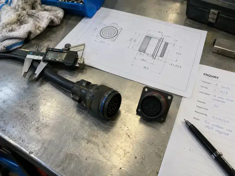
Because the differences between these families are dimensional as much as electrical, a waterproof connector for multiple wires is worth confirming on a sample before a production order. The check that matters is against your actual cable rather than a specification sheet, because that is what catches a gland that will not accept the jacket or a pole arrangement that does not match the circuit. Send the cable outer diameter with your inquiry and the gland range can be checked against it before you order.
Practical answers about multi-wire waterproof connectors, poles, cable entries, splitters, conductor sizes, and system ratings.
A waterproof connector for multiple wires is a connector or enclosure that seals a joint involving more than one conductor or more than one circuit. The two main forms are a multi-pole connector, which carries several isolated circuits through one sealed shell, and a splitter or junction box, which distributes one feed across several cables.
Poles (or pins) are the electrically isolated circuits inside a connector. Ways are the separate cable entries on a junction box. A 4-pole connector takes one cable per side and carries four circuits; a 4-way box takes four separate cables.
Not with a standard multi-pole connector, because each pole runs to a single cable. Use an M685 splitter with a 1-in-2-out configuration, or a junction box, both of which produce two sealed outputs from one input.
The M686 range runs from 2-way to 14-way, with the 14-way model accepting one input and thirteen outputs across separate glands. The practical limit is usually installation space and gland diameter rather than the number of entries.
The M684 and M685 accept 0.5–2.5 mm² (14–20 AWG), and the smaller M682 and M683 accept 0.5–1.5 mm² (18 AWG). Cable outer diameter is a separate limit, ranging from 3 mm to 14 mm depending on series.
The published ratings are AC (450 V under IEC and 300 V under ETL), so a DC application needs the rating confirmed against the datasheet before it is specified. This is standard for this product class and should be checked at design stage, not on site.
Send the number of circuits, conductor size, cable outer diameter, and current, plus whether the joint must be re-enterable. We will come back with the family and model, a quote, and samples for evaluation if you want them. Certification documents are available in our certificates section, and assemblies are inspected before shipment under our quality control process.


LET’S BUILD YOUR CONNECTION SOLUTION
Share your application, specifications, and estimated quantity. Our team will recommend a suitable connector solution and provide a quotation.
Low MOQ · OEM & ODM · Product Selection Support · Fast Quote Response