

Need waterproof connectors?Request a Quote →
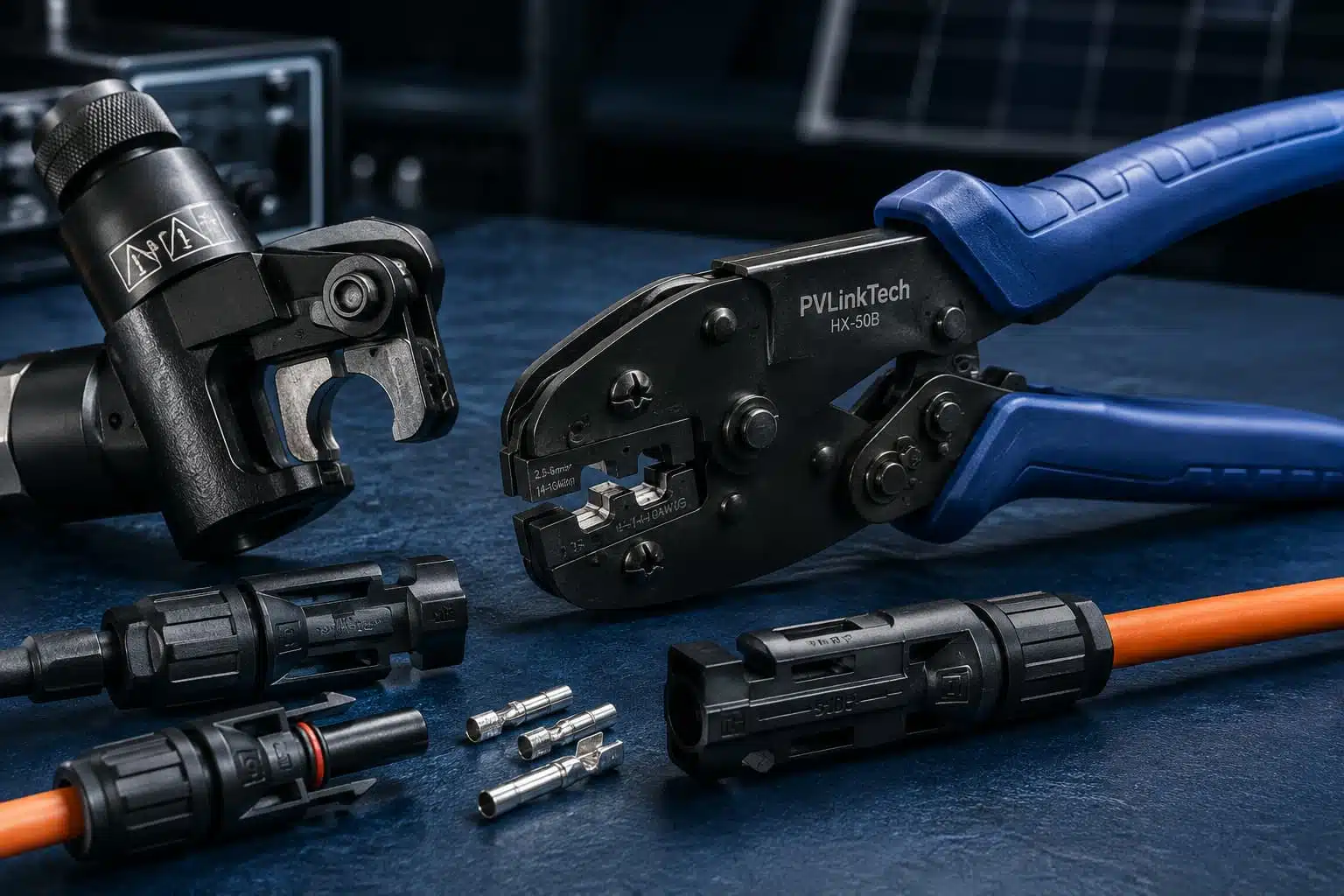
The most common crimping advice on installer forums is “just squeeze it with pliers.” It is also the The most common crimping advice on installer forums is “just squeeze it with pliers.” It is also the advice that produces field failures. This guide covers how to crimp MC4 connectors correctly: which tools to use, how to match wire, contact, and die, an eight-step procedure, and how to verify the result. It is written for PV installers, EPC quality teams, O&M technicians, and procurement managers.
On r/solar and DIY forums, the “pliers and solder” school of crimping is a running theme. Treat that as a counterexample, not a method: a crimp is a certified mechanical–electrical joint, and the certification covers the whole system, not just the housing.
Key Takeaways – A crimp is a certified system — contact, cable, and crimp tool tested together under standards such as IEC 62852 and UL 6703. The tool and die are part of the certification. – Use the manufacturer’s approved ratchet tool with the die matched to the exact cable size; complete the full stroke. – Verify every crimp: visual check, pull test, and records. Do not skip verification on field-made connections. – Soldering is not an acceptable substitute for crimping PV connectors. – On a 120 MW PV plant in Indonesia, controlled factory crimping cut assembly time by about 25% and delivered zero connector-related failures over 18 months.
No. Use the connector manufacturer’s approved crimp tool with the die matched to the exact cable size, and complete the full ratchet stroke. Generic pliers-style crimpers cannot position the contact correctly or apply the required force. The correct way to crimp MC4 connectors is verified — visually, by pull test, and against the certified contact/tool combination — not assumed.
The sections below cover tool selection, matching, the procedure, and verification in the order you need them on site.
The crimped joint is where current transfers from the conductor to the contact. Contact resistance and the gas-tight (cold-weld) connection quality live in that interface. Crimping works by compressing the contact barrel around the conductor so metal-to-metal contact survives decades of thermal cycling — not by squeezing hard enough that it “feels tight.”
Connector standards treat this as a system question. IEC 62852:2014+AMD1:2020 CSV — the standard for connectors in DC circuits of PV systems, rated up to 1,500 V DC and 125 A per contact — and UL 6703 in North America certify a contact, a cable size, and a crimp tool tested together. Change any one element and the certificate no longer covers the combination.
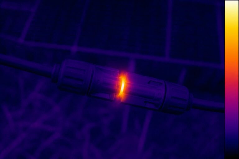
That matters in the field because thermal cycling, vibration, and corrosion stress a bad crimp faster than any housing difference. A 1,500 V system leaves less tolerance for resistance drift than a 600 V one: the same imperfect joint that runs warm at 600 V can run hot at 1,500 V DC. Mixed connector pairs add a second variable — see our guide on /can-you-mix-mc4-connectors/ for the pairing rules.
Three tool classes cover PV work:
Manual ratchet crimpers. The standard for 4 mm² and 6 mm² (≈12 and 10 AWG) PV cable. The ratchet mechanism locks the handles and prevents release until the full stroke is complete — that is the feature that guarantees consistent force. If the tool opens before the stroke finishes, the crimp is incomplete by definition.
Hydraulic or electric tools. Required for large conductors. The PVLinkTech E150–E350 families, which cover 2 AWG to 4/0 AWG (13–20 mm outer diameter), exceed what a manual tool can do consistently. Hydraulic heads apply the force without operator strength as a variable.
Specialized dies and locators. The die set is specific to the contact family. The locator positions the contact in the die so the crimp lands in the right place every time. This is why the manufacturer’s specified tool matters: a generic crimper has no locator, so the contact can sit off-center, and the barrel can deform unevenly.
Before buying, check: die set included, cable range, ratchet release behavior, and compatibility with the contact family you use. A tool that “fits MC4” is not the same as a tool approved for your contact.

Every crimp starts with three numbers that must agree: cable cross-section, contact size, and die size. The contact datasheet lists the approved combinations — use it, not the color of the housing.
| Cable | Contact size | Tool class | Typical use |
|---|---|---|---|
|
4 mm² (≈12 AWG) PV wire |
4 mm² contact | Manual ratchet with matching die | Module strings, home runs |
|
6 mm² (≈10 AWG) PV wire |
6 mm² contact | Manual ratchet with matching die | Longer strings, higher current |
| 16–120 mm² (2 AWG–4/0 AWG) | Large current contact | Hydraulic head, matching die | Utility-scale, E150–E350 families |

Follow these eight steps for every field crimp. The procedure assumes the circuit is isolated and verified de-energized by qualified personnel — never work on live DC circuits, and never disconnect PV connectors under load.
Skip none of these. Steps 6 and 7 are where bad crimps get caught; steps 1, 4, and 5 are where they are created.
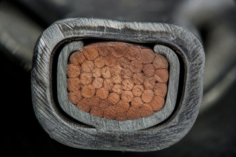
Crimp cross-section: good vs badWhat the die should — and should not — produce

These are the ten mistakes we see most often in field-made connections, with the consequence and the prevention:
| # | Mistake | Consequence | Prevention |
|---|---|---|---|
| 1 | Pliers-style crimping | No locator, uneven force, no stroke guarantee | Use the approved ratchet tool |
| 2 | Wrong die size | Barrel under- or over-compressed | Match die to contact and cable datasheet |
| 3 | Wrong strip length | Exposed conductor or insulation in barrel | Measure to the contact drawing |
| 4 | Crimping over insulation | No copper contact — high resistance, heat | Confirm insulation clears the barrel |
| 5 | Cable/contact mismatch | Loose or cracked strands inside barrel | Verify cable size against contact spec |
| 6 | Double-crimping | Work-hardened barrel, cracks later | One stroke only; re-do with new contact if wrong |
| 7 | Soldering instead of crimping | Solder creeps under heat, voids, hot spots; not certified | Use the certified crimp system |
| 8 | Contact inserted reversed or loose | Intermittent connection or no click at assembly | Follow the drawing; listen for the click |
| 9 | Contaminated or oxidized contact | Higher resistance from day one | Keep contacts sealed until use; no bare handling |
| 10 | Skipping the pull test | Bad crimp goes into the string | Test every field crimp, log the result |
Mistake 7 deserves emphasis because it is popular on forums: soldering PV connectors is not a certified alternative. Solder creeps under thermal cycling, creates voids, and introduces a hot spot exactly where you do not want one. If a crimp tool is not available, stop and get the tool — do not improvise a soldered joint in a DC circuit.

Verification has three levels, from field to lab:
Visual. Indentation centered and symmetric on the barrel; no insulation in the crimp; no loose strands; no cracks or tool marks on the housing after assembly.
Pull test. Apply the force specified in the exact contact and cable datasheet. If the cable pulls out of the contact, the crimp fails — replace the contact and re-crimp. Do not use a “standard” number from memory; every contact family specifies its own force.
Destructive and lab checks. Cross-section micrographs show strand compression and void content; contact-resistance measurement in milliohms confirms the joint is within spec. These are incoming-inspection and qualification tools, not site routines.
Record every result. Incoming inspection and commissioning files should trace each connection to a contact lot, a tool, and an operator — the same records discipline that catches mixed connector pairs before they become field failures. Our quality control page shows the checks we run on production lines.
Factory crimping exists for a reason: the same tool, the same die, the same operator procedure, and a documented pull test on every piece. A pre-crimped cable assembly removes the field variables entirely — no die selection on the roof, no ratchet half-stroke, no question about whether the operator had the right tool in the van.
The field-time saving is measurable. On a 120 MW PV plant in Indonesia that we supplied with PV4 connectors and Y-branch assemblies, controlled factory crimping cut assembly time by about 25% against field crimping, and the project reported zero connector-related failures over 18 months of operation. For large projects, critical strings, and sites with limited tooling, pre-crimped assemblies are often the lower-risk procurement choice.
Compare that discipline against the DIY approach: installers on a solar forum thread describing crimping as “squish them with pliers, solder, and add heatshrink” are describing a connection with no verified force, no verified geometry, and no certification coverage. It can work — until a thermal cycle finds the weak spot.
The connector manufacturer’s approved ratchet crimper, the die matched to the contact and cable size, and a pull-test fixture or force gauge. For large conductors (2 AWG–4/0 AWG), a hydraulic crimp head. The tool must be the one named in the contact datasheet — “MC4-style” tools from other brands are not automatically approved.
No. A generic pliers-style tool has no locator, no ratchet stroke guarantee, and no verified force. The result is an unverified joint with unknown contact resistance. If you do not have the approved tool, stop and get it — an unverified crimp in a DC circuit is not a shortcut, it is a risk.
No. Soldered joints are not part of the certified connector system: solder creeps under thermal cycling, voids form, and the joint becomes a hot spot. Connector standards such as IEC 62852 certify the crimp system — contact, cable, and tool together. A soldered connection has no certificate coverage.
The die size comes from the contact and cable datasheet, not from the connector brand. A 4 mm² (≈12 AWG) cable uses the die listed for that contact and cable combination; 6 mm² (≈10 AWG) uses its own die. Match all three — cable, contact, die — and confirm against the manufacturer’s drawing before crimping.
To crimp MC4 connectors correctly, match the cable, contact, die, and approved crimping tool specified by the connector manufacturer. Strip the cable to the required length, complete the full ratchet stroke, inspect the crimp, perform the specified pull test, and assemble the connector housing according to the manufacturer’s instructions.
Run the three checks: visual (centered indentation, no insulation in the barrel, no loose strands), pull test (force per the exact datasheet — the contact must not move), and records (log tool, die, operator, result). If any check fails, replace the contact and re-crimp with the approved tool.
Knowing how to crimp MC4 connectors correctly starts with treating the crimp as a certified joint, not simply a squeeze. The system that makes it reliable — an approved tool, matched die, correct cable, full stroke, and pull test — is also the system that keeps a 1,500 V string safe for decades. Whether you crimp MC4 connectors on a rooftop or order pre-crimped assemblies, the verification rule is the same: match, stroke, test, record.
If you are specifying connectors for a new project, send us your cable spec and application — we supply pre-crimped cable assemblies and controlled crimping with full traceability, and we will review your connector pairing and crimping plan. Start with the MC4 vs PV4 connector comparison or request a quote directly.

LET’S BUILD YOUR CONNECTION SOLUTION
Share your application, specifications, and estimated quantity. Our team will recommend a suitable connector solution and provide a quotation.
Low MOQ · OEM & ODM · Product Selection Support · Fast Quote Response